
Lancer L4-2.4L SOHC (2005)
STEP 1. Use scan tool MB991958 to select "ECU COMM CHK" on the SWS monitor display.
Check the following ECUs:
-
Column-ECU
-
Front-ECU
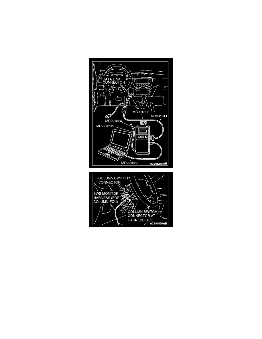
CAUTION: To prevent damage to scan tool MB991958, always turn the ignition switch to the "LOCK" (OFF) position before connecting or
disconnecting scan tool MB991958. Connect the DLC harness before connecting the column-ECU harness. Be sure to connect SWS monitor kit
MB991813 after turning on scan tool MB991958.
1. Connect scan tool MB991958 to the data link connector.
2. Connect SWS monitor kit MB991813 to the column switch connector. (3) Turn the ignition switch to the "ON" position.
4. Operate scan tool MB991958 according to the procedure below to display "ECU COMM CHK.
a. Select "SYSTEM SELECT.
b. Select "SWS.
c. Select "SWS MONITOR.
d. Select "ECU COMM CHK.
5. Scan tool MB991958 should show "OK" on the "ECU COMM CHK" menus for both the "COLUMN ECU" and the "FRONT ECU" menus.
Q: Are "OK" displayed on both the "COLUMN ECU" and "FRONT ECU"?
"OK" are displayed for all the items : Go to Step 2.
"NG" is displayed on the "COLUMN ECU" menu : Refer to Inspection Procedure A-2 "Communication with column switch (column-ECU) is
not possible.
"NG" is displayed on the "FRONT ECU" menu : Refer to Inspection procedure A-4 "Communication with front-ECU is not possible."
STEP 2. Check the input signal by using "FUNCTION DIAG." menu of the SWS monitor.