
Lancer L4-2.4L SOHC (2005)
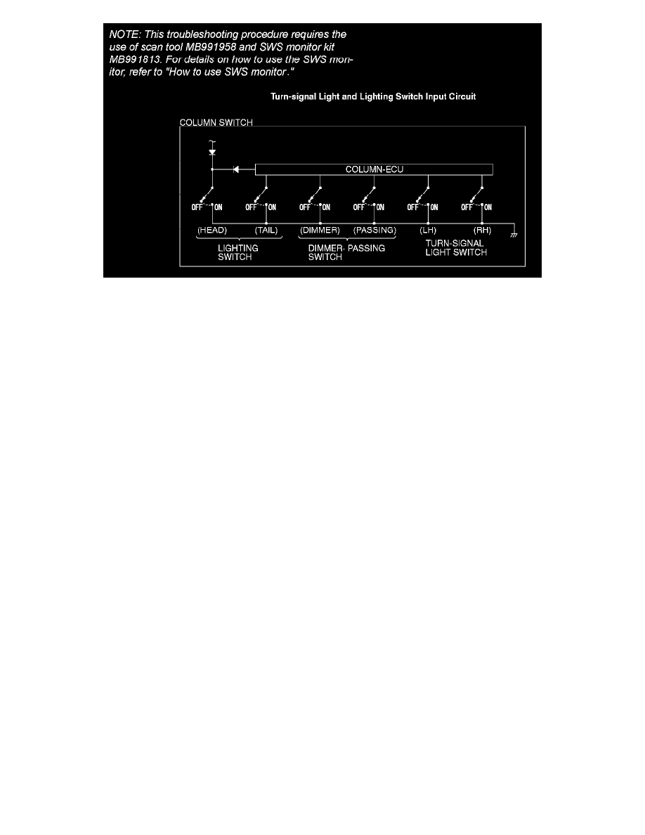
Turn-signal Light And Lighting Switch Input Circuit
CIRCUIT OPERATION
The ETACS-ECU operates the following equipment or functions according to signal from the column switch (turn-signal light and lighting switch):
-
Light reminder tone alarm function
-
Headlight
-
Turn-signal light
TECHNICAL DESCRIPTION (COMMENT)
If the signal is not normal, the equipment or functions, which are described in "CIRCUIT OPERATION", do not work normally. If the signal is not
normal, the column switch (turn-signal light and lighting switch) or the ETACS-ECU may be defective.
TROUBLESHOOTING HINTS
-
The column switch (turn-signal light and lighting switch) may be defective
-
The ETACS-ECU may be defective
-
The wiring harness or connectors may have loose, corroded, or damaged terminals, or terminals pushed back in the connector
DIAGNOSIS
Required Special Tools:
-
MB991223: Harness Set
-
MB991958: Scan Tool (MUT-III Sub Assembly)
-
MB991824: Vehicle Communication Interface (V.C.I.)
-
MB991827: MUT-III USB Cable
-
MB991911: MUT-III Main Harness B
-
MB991813: SWS Monitor Kit
-
MB991806: SWS Monitor Cartridge
-
MB991812: SWS Monitor Harness (For Column-ECU)
-
MB991922: Probe Harness
STEP 1. Use scan tool MB991958 to select "ECU COMM CHK" on the SWS monitor display.
Check the column-ECU.
CAUTION: To prevent damage to scan tool MB991958, always turn the ignition switch to the "LOCK" (OFF) position before connecting or
disconnecting scan tool MB991958. Connect the DLC harness before connecting the column-ECU harness. Be sure to connect SWS monitor kit
MB991813 after turning on scan tool MB991958.