
Lancer LS L4-2.0L SOHC (2002)
STEP 6. Check the combination meter (printed-circuit board).
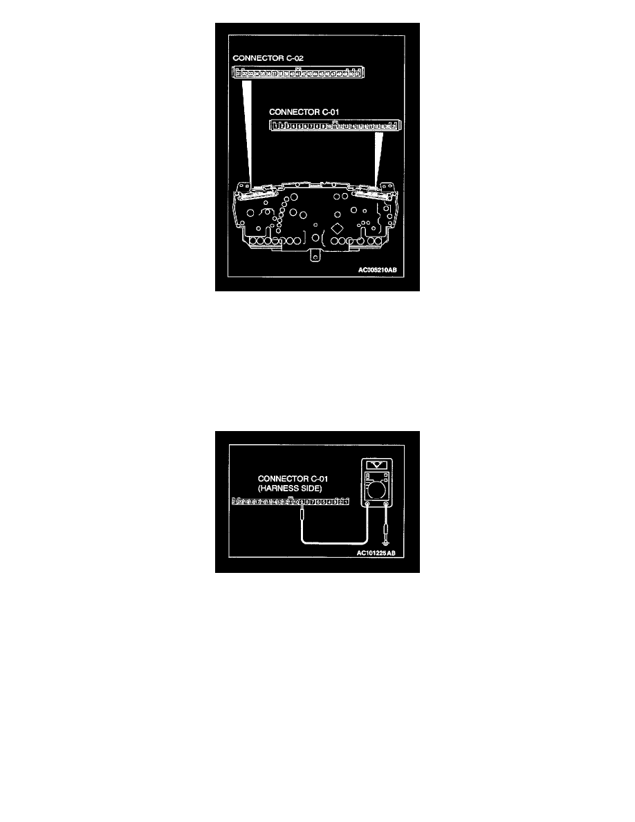
1. Remove the combination meter.
2. Remove the seat belt warning light bulb. Then measure the resistance value between the bulb terminals.
3. Install the bulb to the combination meter, and then measure the resistance value between connector C-01 terminal 9 and connector C-02 terminal
35. The measured resistance value should be roughly the same as the value measured in Step 2.
Q: Are these two resistance values extremely different?
YES: Repair or replace the combination meter (printed circuit board). Check that the seat belt warning light illuminates normally.
NO (much the same): Go to Step 7.
STEP 7. Measure at combination meter connector C-01 in order to check the ignition switch (IG1) line of the power supply to the combination
meter.
1. Disconnect combination meter connector C-01, and measure at the wiring harness side.
2. Turn the ignition switch to the "ON" position.
3. Measure the voltage between terminal 9 and ground.
-
The measured value should be approximately 12 volts (battery positive voltage).
Q: Does the measured voltage correspond with this range?
YES: Go to Step 10.
NO: Go to Step 8.