
Mirage L4-1468cc 1.5L SOHC (1993)
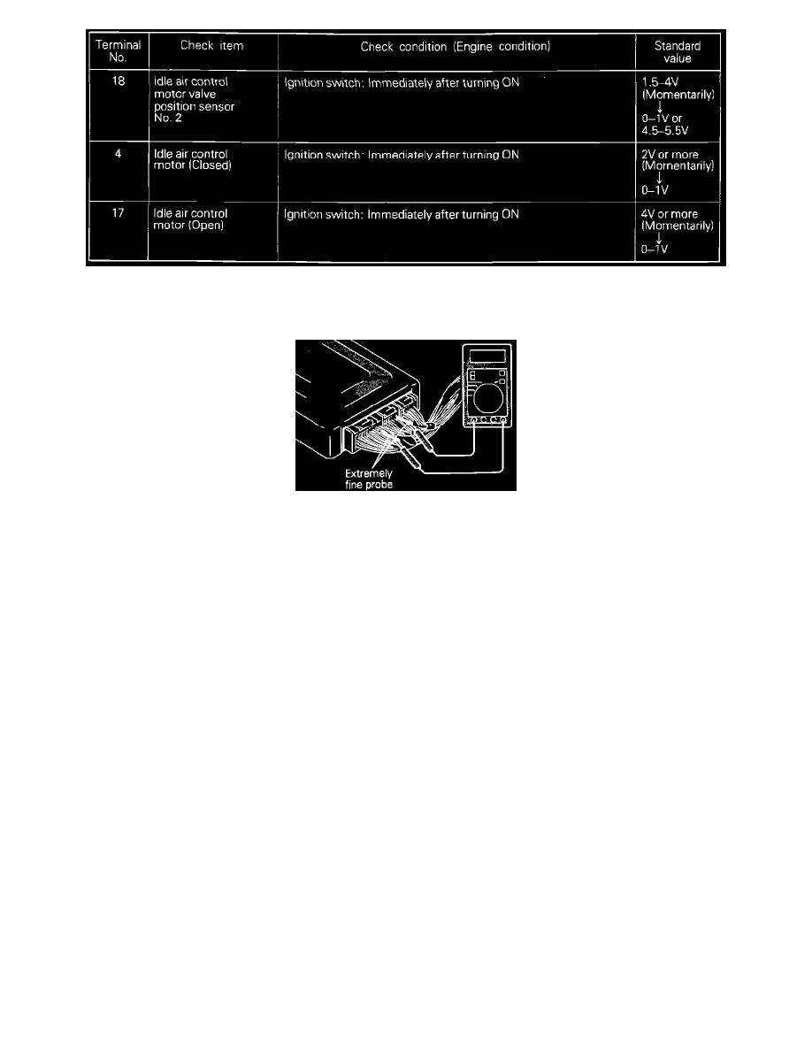
Terminal Voltage Chart
Connect a very thin probe (such as a paper clip) to the positive lead of the voltmeter.
Insert the probe from the wire side of the connector, and compare the measured voltage to the corresponding pin on the chart.
NOTE:
-
Measure voltages with engine control module connectors connected.
-
Use the ground pin (terminal # 106) as the ground for the voltmeter.
If voltage measured differs from that listed on the chart, check the corresponding sensor, actuator, or related electrical circuit. After repairs have
been completed, recheck voltmeter readings to confirm that the repair has corrected the problem.