
Montero Endeavor 4WD V6-3.5L SOHC (2000)
CONNECTOR CONTINUITY AND VOLTAGE TEST
Follow the steps below to avoid causing poor connector contact and/or reduced waterproof performance of connectors when checking continuity and/or
voltage at connectors of waterproof connectors.
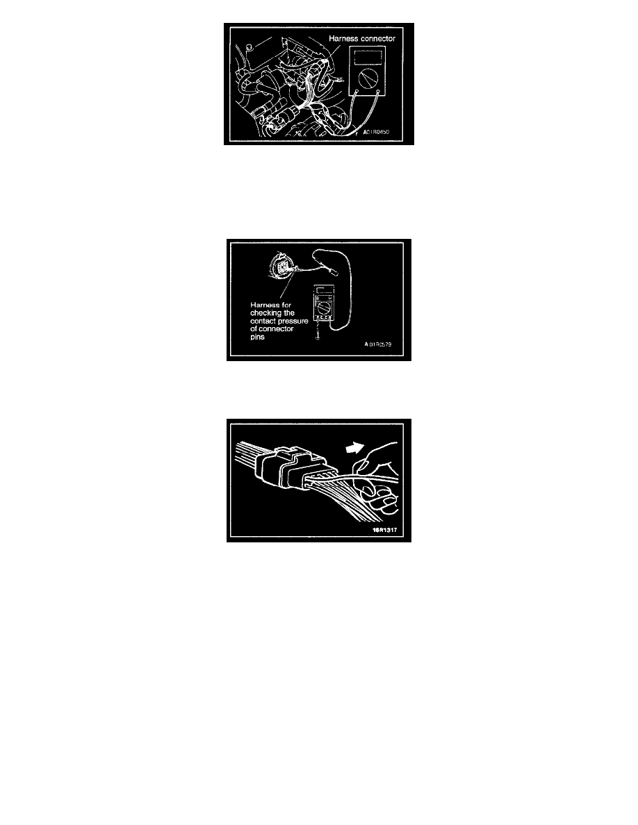
1. If checking is performed with the circuit in the stale of continuity, be sure to use the special tool (harness connector). Never insert a test bar from
the harness side, because to do so will reduce the waterproof performance and result in corrosion
2. If the connector is disconnected for checking and the facing part is the female pin side, the harness for checking the contact pressure of connector
pins should be used. Never force the insertion of a test bar, because to do so will cause poor or improper contact.
3. If the facing part is the male pin side, contact the test bar directly to the pins. Care must be taken not to short-circuit the connector pins.
IMPROPER TERMINAL ENGAGEMENT CHECK
When the terminal stopper of the connector is out of order, engagement of the male and female terminals becomes improper even when the connector
itself is engaged perfectly and terminal sometimes slips out to rear side of connector. Make sure, that each terminal does not come off the connector by
pulling each harness wire.
CONNECTOR TERMINAL ENGAGEMENT AND DISENGAGEMENT
A connector that engages loosely can be repaired by removing the female terminal from the connector housing and raising its lance to establish securer
engagement. Removal of the connector terminal used for MFI and ELC-4 A/T control circuit can be done in the following manner.
COMPUTER CONNECTOR