
Montero Sport 2WD V6-3.0L SOHC (1997)
NOTE: Only loosen the tie rod end mounting nut; but do not remove it from the ball joint.
Use special tool MB990635 or MB991113 to disconnect the ball joint.
INSPECTION
1. Check the rubber parts for cracks and break.
2. Dust cover check. If there are any cracks in or damage to the dust cover, replace the tie rod end assembly or idler arm. If the dust cover is damaged
accidentally during service work, replace the dust cover only.
INSTALLATION
Installation in reverse order as removal.
NOTE: Installation service points as follows:
a. Tie rod assembly installation (2).
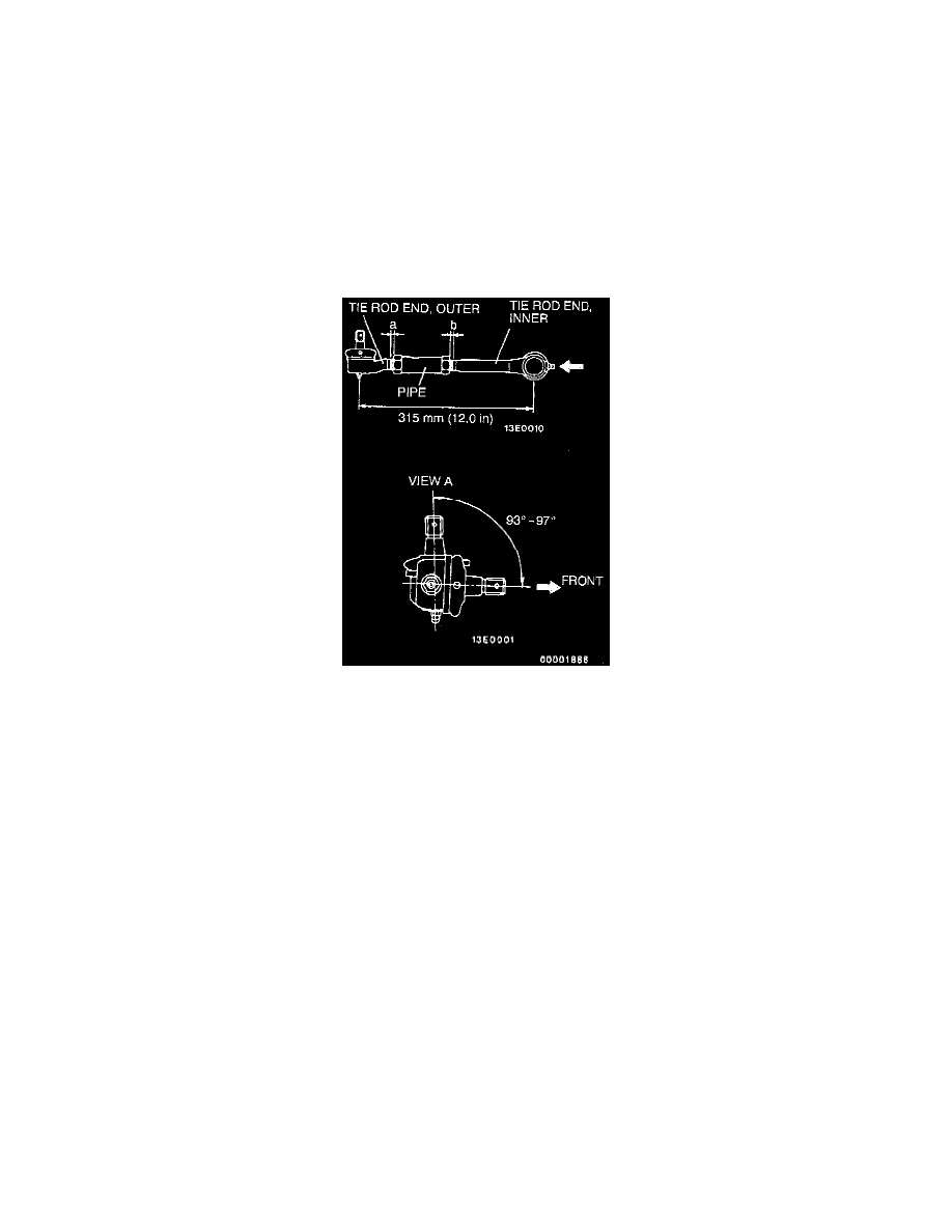
CAUTION: The outer end of the tie rod end has a left thread.
NOTE: The illustration at left shows the left side tie rod assembly. The right side tie rod assembly is symmetrical to the left side assembly.
1. Install the tie rod assembly so that the dimension is as shown in the illustration.
NOTE: Fully tighten the lock nut after the tie rod assembly is installed to the body and the toe-in has been adjusted.
2. Adjust the pipe so that the difference between dimensions (a) and (b) is 1.5 mm (0.059 inch) or less, and then temporarily tighten the lock
nut.
b. After installation steps do the following:
1. Check steering wheel position with the wheels straight ahead.
2. Front wheel alignment.
Overhaul