
Montero Sport XLS 4WD V6-3.0L SOHC (1999)
NOTE: After inspecting IOD storage connector A-54X and junction block connector D-01, inspect the wire. If IOD storage connector A-54X or
junction block connector D-01 is damaged, repair or replace it
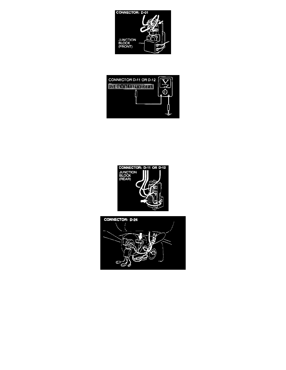
STEP 17. Check the input signal from the column switch (lighting switch).
1. Remove the ETACS-ECU or tone alarm-ECU and measure at the junction block side (connector D-11 or D-12).
2. Turn the lighting switch on ("TAIL' or "HEAD" position).
3. Measure the voltage between terminal number 5 and body ground.
Voltage should be approximately 12 volts (battery positive voltage).
If any circuit check made at connector D-11 or D-12 does not meet specifications, go to Step 18.
If any circuit check made at connector D-11 or D-12 meets specifications, check that the malfunction is eliminated.
STEP 18. Check the harness wires between ETACS-ECU connector D-11 or tone alarm-ECU connector D-12 and column switch connector
D-24.
If the harness wires between ETACS-ECU connector D-1 1 or tone alarm-ECU connector D-12 and column switch connector D-24 are damaged, repair
them, check that the malfunction is eliminated.