Montero Sport XLS 4WD V6-3.5L SOHC (2002)

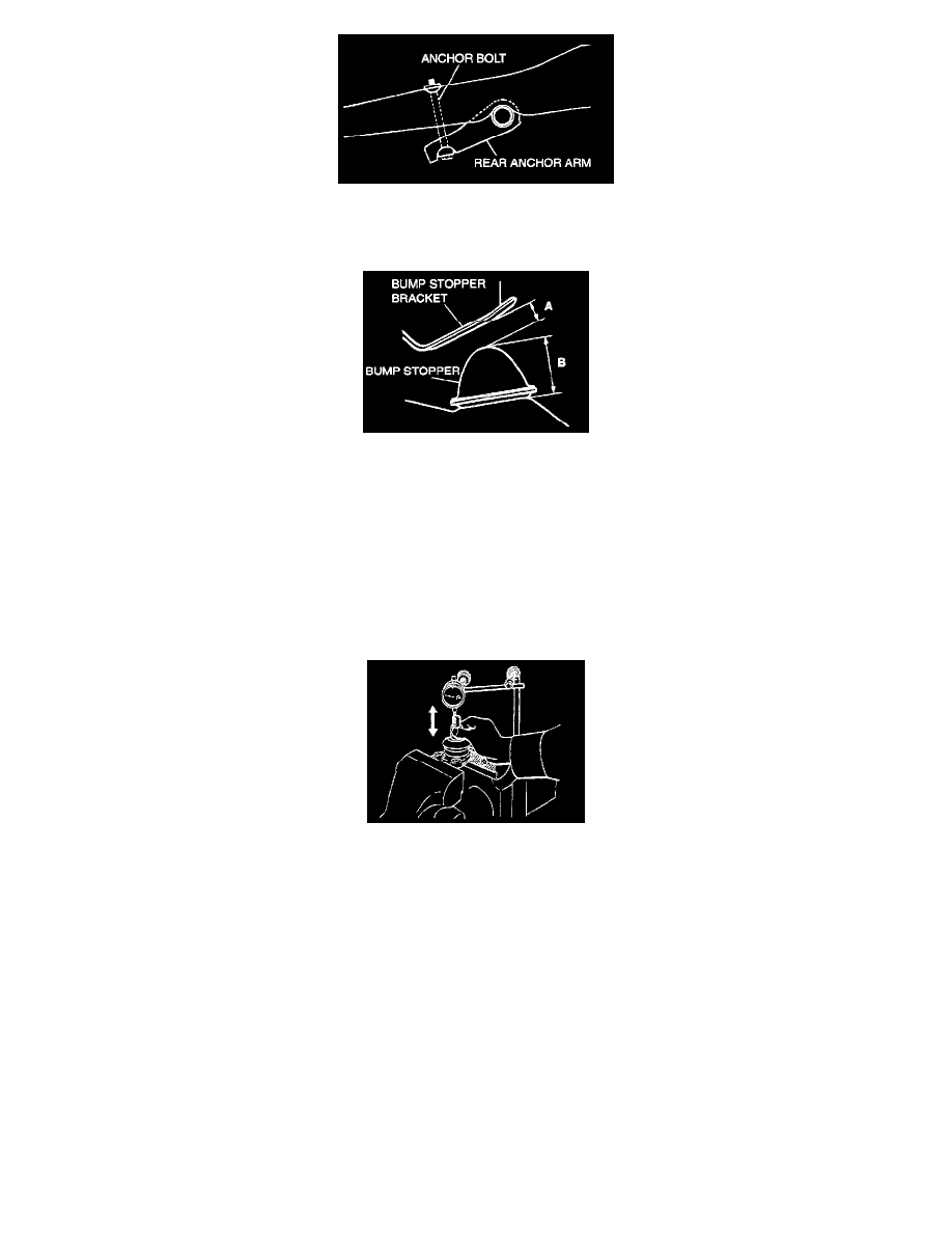
3. Mount the anchor bolt as shown in the illustration, and install the rear anchor arm adjusting nut.
>>B<< BUMP STOPPER AND BUMP STOPPER BRACKET CLEARANCE ADJUSTMENT
1. With the vehicle in an unladen condition, dimension A from the bump stopper to the bump stopper bracket should be 18 - 20 mm (0.71 - 0.79
inch).
NOTE: Dimension A will be 18 mm (0.71 inch) (B = 50 mm [2.0 inches]) when the bump stopper is a new part. When the bump stopper is
worn and becomes less than 50 mm (2.0 inches), dimension A will increase by the decreased amount.
2. If dimension A is not 18 - 20 mm (0.71 - 0.79 inch), adjust the anchor arm assembly adjusting nut.
INSPECTION
LOWER ARM BALL JOINT END PLAY
Check the lower arm ball joint assembly end play by following the steps.
1. Measure the lower arm ball joint assembly end play with a dial indicator.
Limit: 0.3 mm (0.01 inch)
2. If the lower arm ball joint assembly end play exceeds the limit, replace the lower arm ball joint assembly.
LOWER ARM BALL JOINT DUST COVER CHECK
1. Press the dust cover with a finger to check whether the dust cover is cracked or damaged.
2. When dust cover is cracked or damaged, replace the lower arm ball joint assembly.
NOTE: If the dust cover is cracked, the ball joint could be damaged, so if the dust cover is damaged during maintenance work, replace it.
REAR LOWER ARM BUSHING REPLACEMENT
