
Montero Sport XS 2WD V6-3.5L SOHC (2001)
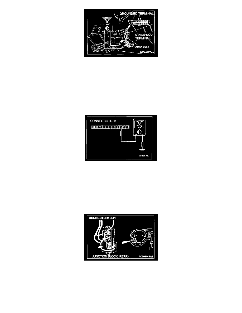
STEP 2. Check the input signal from the ignition switch (by using a voltmeter).
Check the input signals from the following switches:
1. Use special tool MB991529 to connect a voltmeter between ground terminal 4 or 5 and ETACS-ECU terminal 9 of the data link connector.
2. Check that the voltmeter indicator deflects once when the ignition key is moved from the "LOCK" position to the "ON" position.
Q: Does the voltmeter indicator deflect?
YES: Replace the ETACS-ECU. Check that the malfunctions eliminated.
NO: Go to Step 3.
STEP 3. Check the input signal from the driver's side door switch.
1. Disconnect the ETACS-ECU connector D-11 and measure at the junction block side.
2. Turn the ignition switch "ON".
3. Measure the voltage between terminal number 3 and ground.
Q: Is the voltage approximately 12 volts (battery positive voltage)?
YES: Replace the ETACS-ECU. Check that the malfunction is eliminated.
NO: Go to Step 4.
STEP 4. Check the ETACS-ECU connector D-11 for damage.
Q: IS the ETACS-ECU connector D-11 in good condition?
YES: Go to Step 5.
NO: Repair or replace it. Refer to Harness Connector Inspection.