
Montero XLS 4WD V6-3.5L SOHC (2001)
YES: Go to Step 4.
NO: Check the relevant input circuit.
STEP 3. Check the input signal (by using a voltmeter).
Check the input signals from the following switches:
-
Ignition switch (IG1)
-
Key reminder switch
-
Driver's door switch
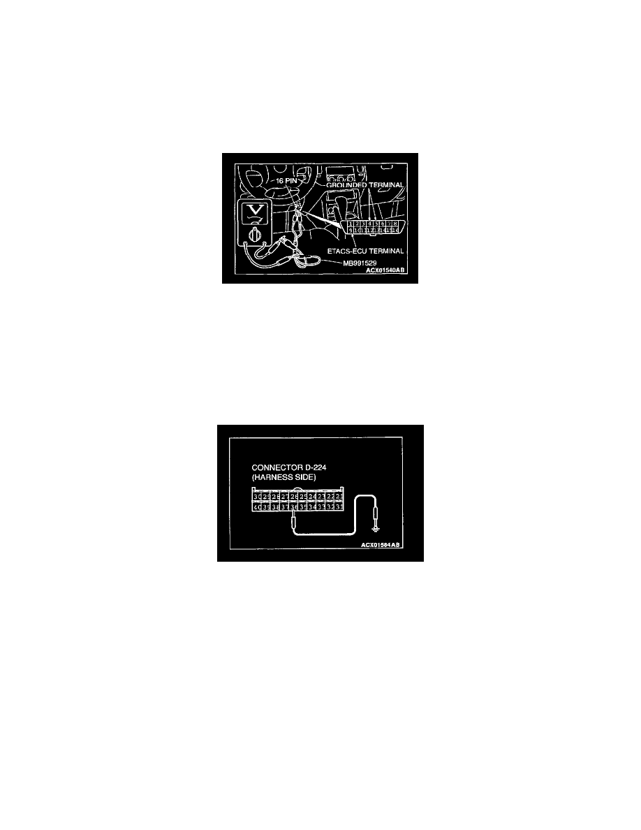
1. Use special tool MB991529 to connect a voltmeter between ground terminal 4 or 5 and ETACS-ECU terminal 9 of the data link connector.
2. Check that the voltmeter indicator deflects once when the input signal enters.
Q: Does the voltmeter indicator deflect?
YES: Go to Step 4.
NO: Check the relevant input circuit.
STEP 4. Check the ignition key hole illumination light circuit at the ETACS-ECU connector D-224.
1. Disconnect the ETACS-ECU connector D-224 and measure at the harness side.
2. Connect terminal 36 to the ground.
Q: Does the ignition key hole illumination light illuminate?
YES: Replace the ETACS-ECU. The ignition key hole illumination light should work normally.
NO: Go to Step 5.
STEP 5. Check the ignition key hole illumination light bulb.
Q: Is the ignition key hole illumination light bulb in good condition?
YES: Go to Step 6.
NO: Replace it. The ignition key hole illumination light should work normally.
STEP 6. Check the key reminder switch (ignition key hole illumination light circuit).
1. Disconnect the key reminder switch connector D-202.
2. Remove the ignition key hole illumination light bulb. Then measure the resistance between the bulb terminals.