
Montero XLS 4WD V6-3.5L SOHC (2001)
YES: Carry out the troubleshooting by referring to Diagnostic Trouble Code Chart.
NO: Go to Step 2 <when using scan tool MB991502> or 3 <when using a voltmeter>.
STEP 2. Check the input signal (by using scan tool MB991502).
Check the input signal from the taillight switch.
CAUTION: To prevent damage to scan tool MB991502, always turn the ignition switch to the "LOCK" (OFF) position before connecting or
disconnecting scan tool MB991502.
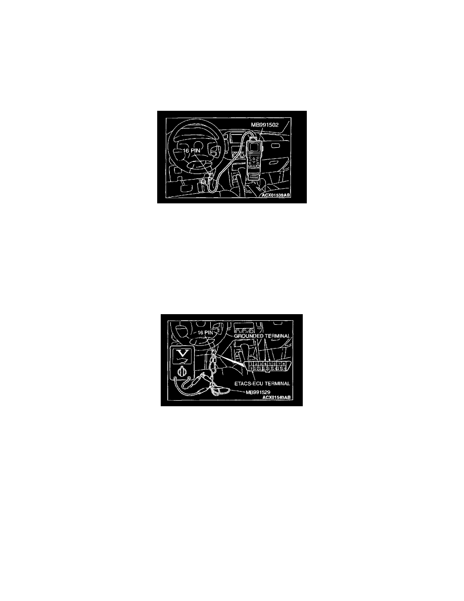
1. Connect scan tool MB991502 to the data link connector.
2. Check that the tone alarm of scan tool MB991502 sounds when the input signal enters.
Q: Does the tone alarm of scan tool MB991502 sound when the input signal enters?
YES: Go to Step 4.
NO: Check the taillight switch input signal circuit. Refer to Inspection Procedure Q-14.
STEP 3. Check the input signal (by using a voltmeter).
Check the input signal from the taillight switch.
1. Use special tool MB991529 to connect a voltmeter between ground terminal 4 or 5 and ETACS-ECU terminal 9 of the data link connector.
2. Check that the voltmeter indicator deflects once when the input signal enters.
Q: Does the voltmeter indicator deflect?
YES: Go to Step 4.
NO: Check the taillight switch input signal circuit. Refer to Inspection Procedure Q-14.
STEP 4. Check the front-ECU power supply circuit (for taillight relay) at front-ECU connector A-07X.
1. Disconnect front-ECU connector A-07X and measure at the relay box side.