
Montero XLS 4WD V6-3.5L SOHC (2001)
1. Connect scan tool MB991502 to the data link connector.
2. Check that the tone alarm of scan tool MB991502 sounds when the input signal enters.
Q: Does the tone alarm of scan tool MB991502 sound when the input signal enters?
YES: Go to Step 4.
NO: Check the fog light input signal circuit. Refer to Inspection Procedure Q-5.
STEP 3. Check the input signal (by using a voltmeter).
Check the input signals from the fog light switch.
1. Use special tool MB991529 to connect a voltmeter between ground terminal 4 or 5 and ETACS-ECU terminal 9 of the data link connector.
2. Check that the voltmeter indicator deflects once when the input signal enters.
Q: Does the voltmeter indicator deflect?
YES: Go to Step 4.
NO: Check the fog light input signal circuit. Refer to Inspection Procedure Q-5.
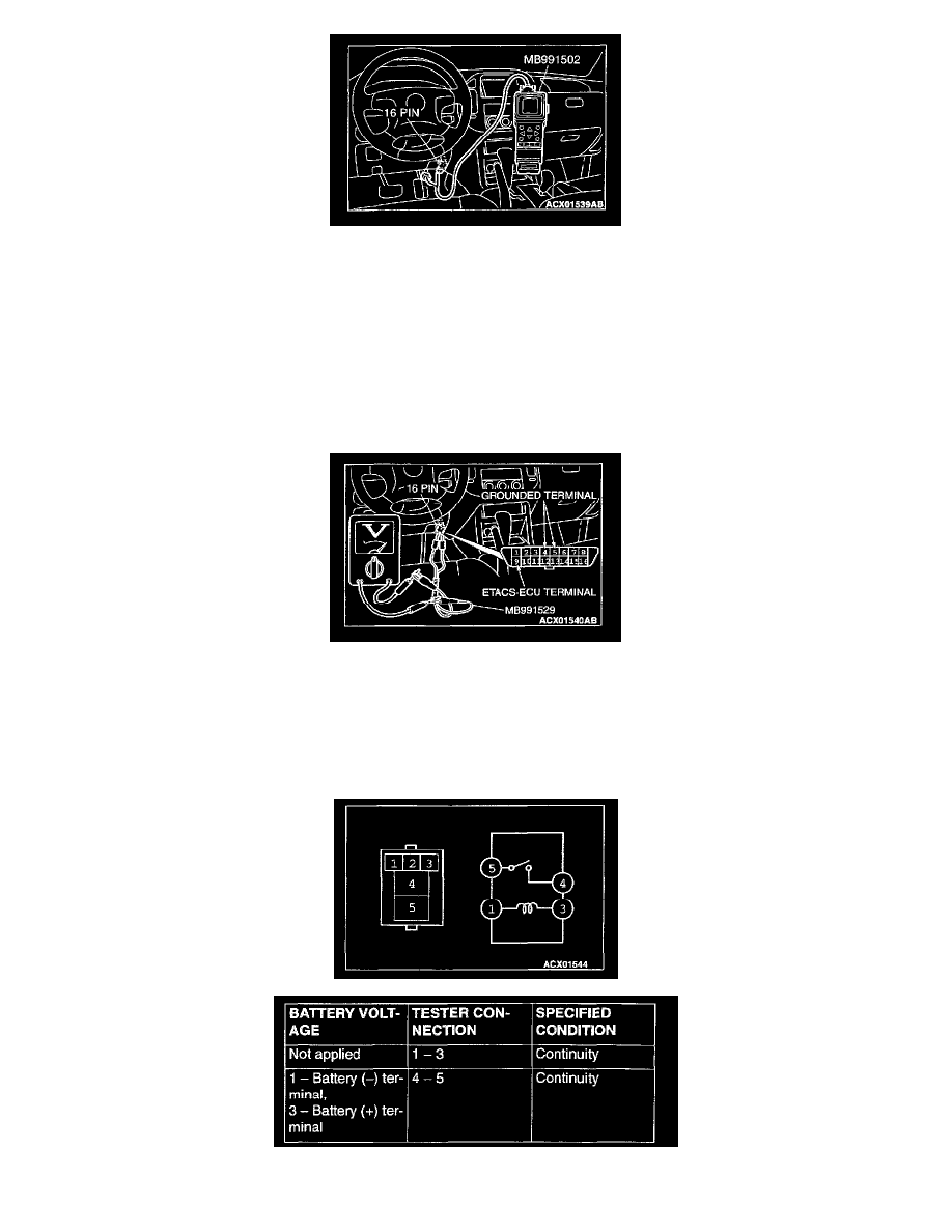
STEP 4. Check the fog light relay.