
Alignment (Front): Service and Repair
- Make
- Mitsubishi
- Model
- Outlander AWD
- Engine
- L4-2.4L SOHC
- Year
- 2003
- Section
- Alignment › Service and Repair › Front
Alignment: Service and Repair
Front
FRONT WHEEL ALIGNMENT CHECK AND ADJUSTMENT
Measure wheel alignment with alignment equipment on a level surface. The front suspension, steering system, wheels, and tires should be serviced to
normal condition before measuring wheel alignment.
TOE-IN
Standard value: 1 ± 2 mm (0.04 ± 0.09 inch)
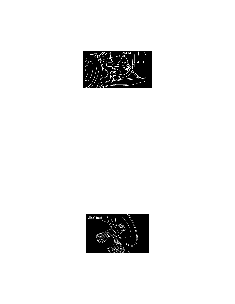
1. Adjust the toe-in by undoing the clip and jam nut, and turning the left and right tie rod turnbuckles by the same amount (in opposite directions).
NOTE: The toe will move out as the left turnbuckle is turned toward the front of the vehicle and the right turnbuckle is turned toward the rear of
the vehicle.
2. Install the clip and tighten the jam nut to the specified torque.
Tightening torque: 52 ± 2 Nm (38 ± 2 ft. lbs.)
3. Confirm that the toe-in is at the standard value.
4. Use a turning radius gauge to check that the steering angle is at the standard value.
STEERING ANGLE
Standard value:
34°50' ± 1°30' <Inner wheel>
29°20' <Outer wheel (reference)>
CAMBER, CASTER AND KINGPIN INCLINATION
Required Special Tool:
^
MB991004: \Wheel Alignment Gauge Attachment <Vehicles with aluminum wheels>
Standard value:
Camber 0° 00' ± 30' (Left/right deviation within 30')
Caster 3° 10' ± 30' (Left/right deviation within 30')
Kingpin inclination 12° 05' ± 1° 30'
NOTE: Camber and caster are preset at the factory and cannot be adjusted.
CAUTION: Never subject the wheel bearings to the vehicle load when the drive shaft nuts are loosened.
NOTE: For vehicles with aluminum type wheels, attach the camber/caster/kingpin gauge to the driveshaft by using the special tool MB991004.
Tighten the special tool MB991004 to the same torque 245 ± 29 Nm (181 ± 21 ft. lbs.) as the driveshaft nut.
LOWER ARM BALL JOINT END PLAY CHECK
1. Raise the vehicle.
2. Remove the stabilizer link from the lower arm.
3. Move the lower arm up and down with your hands to check for an excessive play in the axial direction of the ball joint. If there is an excessive
play, replace the lower arm assembly.
Pinch or Ctrl + scroll to zoom. Double-tap to reset.
Parts & tools for this job For 2003 Mitsubishi Outlander 2.4L
- TOOLTie rod end toolSearch: tie rod end puller
- TOOLBall joint separatorSearch: ball joint separator
- FLUIDPower steering fluidSearch: Mitsubishi power steering fluid
Links open Amazon search results in a new tab. As an Amazon Associate I earn from qualifying purchases.