
Outlander AWD L4-2.4L SOHC (2003)
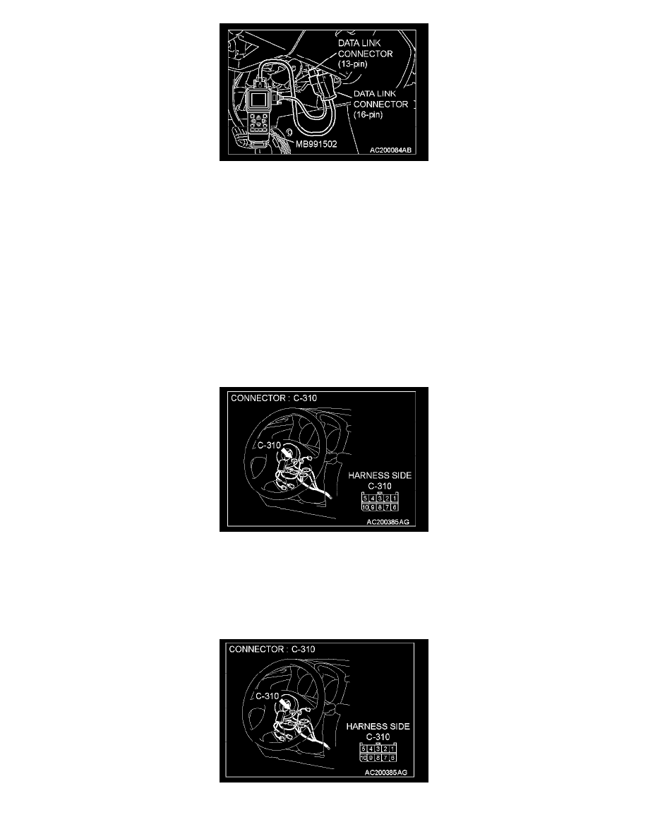
1. Connect scan tool MB991502 to the data link connector (16-pin).
2. Connect SWS monitor kit MB991862 to the data link connector (13-pin).
3. Turn the ignition switch to the "LOCK" (OFF) position.
4. Operate the scan tool MB991502 according to the procedure below to display "ECU COMM CHECK."
1. Select "SYSTEM SELECT."
2. Select "SWS."
3. Select "SWS MONITOR."
4. Select "ECU COMM CHK".
5. Scan tool MB991502 should show "OK" on the "ECU COMM CHK" menus for both the "ETACS ECU" and the "COLUMN ECU" menus.
Q: Is "OK" displayed on both the "ETACS ECU" and "COLUMN ECU" menus?
"OK" are displayed for all the items : Go to Step 2.
"NG" is displayed on the "COLUMN ECU" menu : Go to step 6.
"NG" is displayed on the "ETACS ECU" menu : Refer to Inspection Procedure A-3 "Communication with ETACS-ECU is not possible."
"NG" are displayed for all the items : Refer to Inspection Procedure A-3 "Communication with ETACS-ECU is not possible."
STEP 2. Check column switch connector C-310 for loose, corroded or damaged terminals, or terminals pushed back in the connector.
Q: Is column switch connector C-310 in good condition?
YES: Go to Step 3.
NO: Repair or replace the damaged components). The system should communicate with the column switch (column-ECU) normally.
STEP 3. Check the battery power supply circuit to the column switch. Test at column switch connector C-310.
1. Column switch connector C-310 and measure the voltage available at the wiring harness side of the connector.