
Outlander AWD L4-2.4L SOHC (2003)
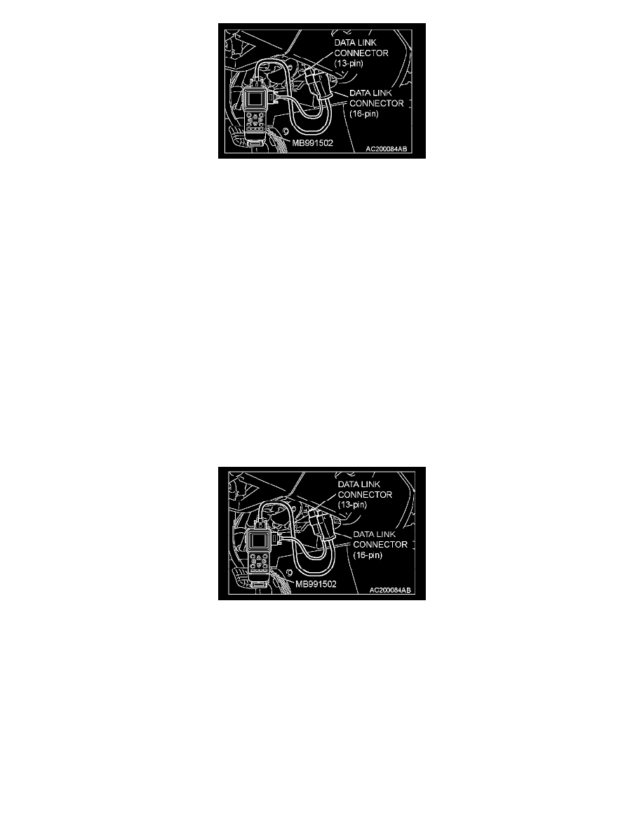
1. Connect scan tool MB991502 to the data link connector (16-pin).
2. Connect SWS monitor kit MB991862 to the data link connector (13-pin).
3. Turn the ignition switch to the "LOCK" (OFF) position.
4. Operate the scan tool MB991502 according to the procedure below to display "ECU COMM CHECK."
1. Select "SYSTEM SELECT."
2. Select "SWS."
3. Select "SWS MONITOR."
4. Select "ECU COMM CHK".
5. Scan tool MB991502 should show "OK" on the "ECU COMM CHK" menus for both the "ETACS ECU" and the "COLUMN ECU" menus.
Q: Is "OK" displayed on both the "ETACS ECU" and "COLUMN ECU" menus?
"OK" are displayed for all the items : Go to Step 2.
"NG" is displayed on the "ETACS ECU" menu : Refer to Inspection Procedure A-3 "Communication with ETACS-ECU is not possible."
"NG" is displayed on the "COLUMN ECU" menu : Refer to Inspection Procedure A-2 "Communication with column switch (column-ECU) is not
possible."
STEP 2. Check the input signal by using "FUNCTION DIAG." menu of the SWS monitor.
Check the input signals from the following switches:
-
Ignition switch: OFF (key removed)
-
Lighting switch: TAIL or HEAD
-
Driver's door: open
-
Front passenger's door: closed
Operate the scan tool MB991502 according to the procedure below to display "LGT MONI. ALRM."
1. Select "SYSTEM SELECT."
2. Select "SWS."
3. Select "SWS MONITOR."
4. Select "FUNCTION DIAG."
5. Select "BUZZER."
6. Select "LGT MONI. ALRM"