
Outlander AWD L4-2.4L SOHC (2003)
1. Connect scan tool MB991502 to the data link connector (16-pin).
2. Connect SWS monitor kit MB991862 to the data link connector (13-pin).
3. Turn the ignition switch to the "LOCK" (OFF) position.
4. Operate the scan tool MB991502 according to the procedure below to display "ECU COMM CHECK."
1. Select "SYSTEM SELECT."
2. Select "SWS."
3. Select "SWS MONITOR."
4. Select "ECU COMM CHK".
5. Scan tool MB991502 should show "OK" on the "ECU COMM CHK" menu for the "ETACS ECU" menu.
Q: Is "OK" displayed on the "ETACS ECU" menu?
YES: Go to Step 2.
NO: Refer to Inspection Procedure A-3 "Communication with ETACS-ECU is not possible."
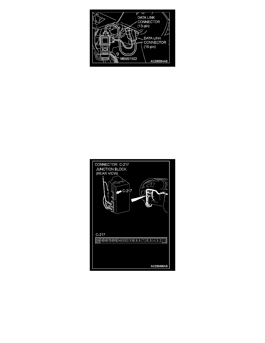
STEP 2. Check the battery power supply circuit to the ETACS-ECU. Test at ETACS-ECU connector C-217.
1. Disconnect ETACS-ECU connector C-217 and measure the voltage available at the junction block side of the connector.