
Precis L4-1468cc 1.5L SOHC (1993)
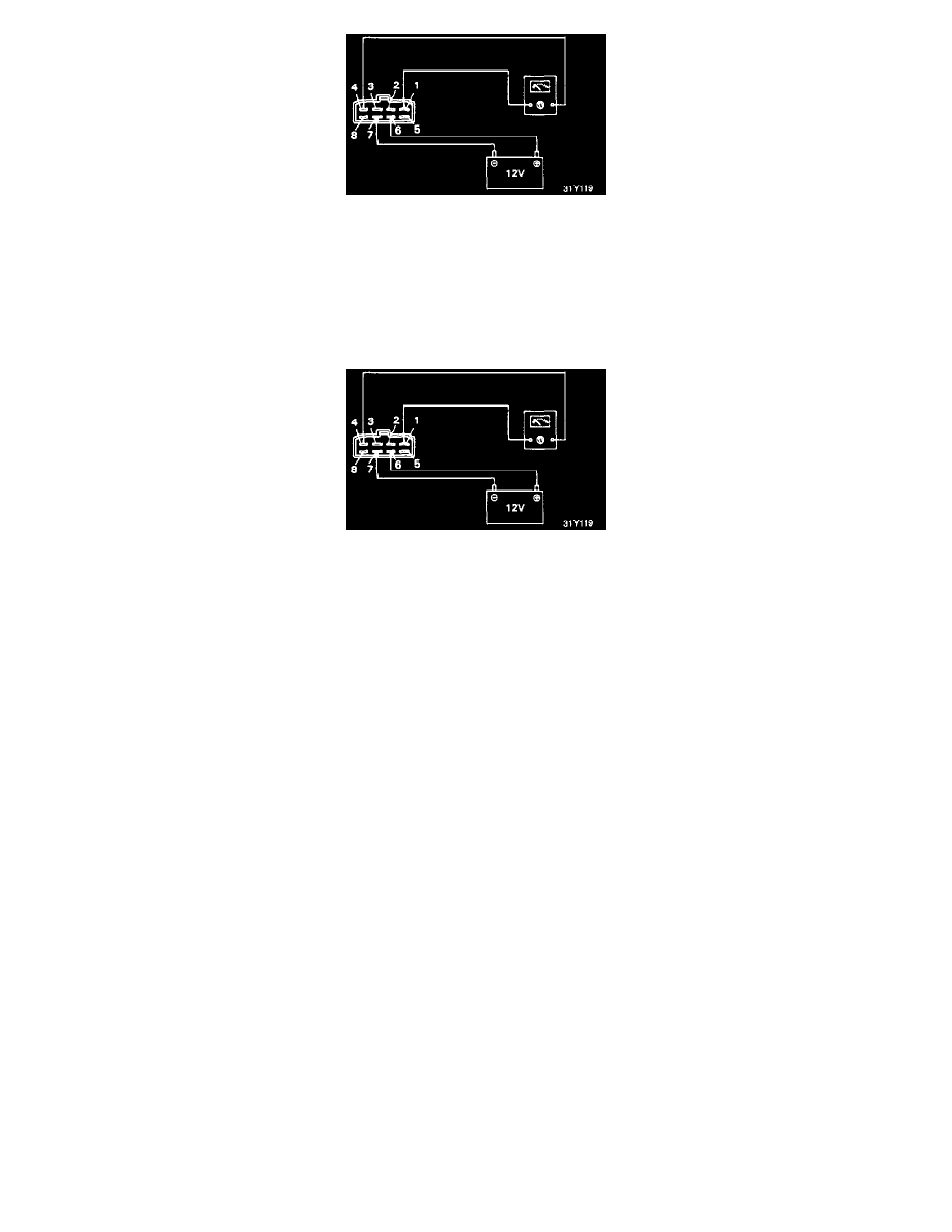
Apply positive power to terminal 6 with negative power applied to terminal 7.
Check terminals 1 and 4: should be conductive (0 ohm).
Remove power.
To test coil L3:
Check terminals 1 and 2, should be non-conductive (infinite ohm).
Check terminals 7(+) and 5(-), should be non-conductive (infinite ohm).
Check terminals 5(-) and 7(+), should be conductive (0 ohm).
Apply positive power to terminal 5 with negative power applied to terminal 7.
Check terminals 1 and 2, should be conductive (0 ohm)
Remove power.
Test between each terminal and the case: All terminals should be non-conductive (infinite ohm).
2.
If the results are not satisfactory, replace the control relay.
POWER AND GROUND CIRCUIT
1.
Disconnect the control relay.
2.
Using a volt meter, check for voltage at the relay connector harness terminal between the white/blue wire and ground.
Voltage
System voltage.
3.
Turn the key to the ON position.
4.
Using a volt meter, check for voltage at the relay connector harness terminal between the black/white wire and ground.
Voltage
System voltage.
5.
Turn the key to the START position.
6.
Using an volt meter, check for voltage at the relay connector harness terminal between the:
A/T black/green wire and ground.
M/T black/yellow wire and ground.
Voltage
System voltage.
7.
Using an ohm meter, check for continuity at the relay connector harness terminal between the black wire and ground.
Continuity
Should exist.