
Precis L4-1468cc 1.5L SOHC (1993)
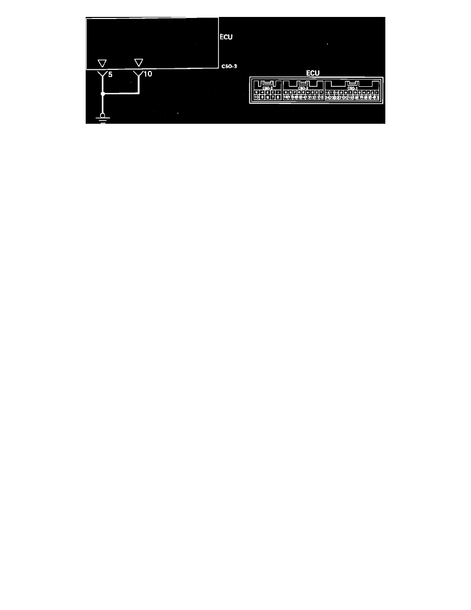
ECU GROUND Circuit
8.
Turn the key off, disconnect the negative battery cable and disconnect the ECU connectors.
9.
Using an ohm meter, check for continuity between the ECU harness connector C50-3 terminal 5 (black wire) and ground.
Continuity
Should exist.
10. Using an ohm meter, check for continuity between the ECU harness connector C50-3 terminal 10 (black wire) and ground.
Continuity
Should exist.
M/T ONLY
11. Using an ohm meter, check for continuity between the ECU harness connector C50-3 terminal 2 (black wire) and ground.
Continuity
Should exist.
12. Connect the negative battery cable and install the control relay.
13. Using a volt meter, check for voltage at the ECU harness connector C50-3 terminal 3 (blue/white wire) and ground.
Voltage
System voltage.
14. Using a volt meter, check for voltage at the ECU harness connector C50-3 terminal 9 (red wire) and ground.
Voltage
System voltage.
15. Using a volt meter, check for voltage at the ECU harness connector C50-3 terminal 4 (red wire) and ground.
Voltage
System voltage.
If any of the previous tests produce unsatisfactory results, the harness will need to be repaired or replaced. Once repairs have been completed, road
test the vehicle to confirm that the repair has corrected the problem.
If the same problem reoccurs, it is possible that there is an intermittent failure of the component or the ECU. Check for looseness at all harness
junctions and test for an intermittent failure.
Engine Control Module (ECM)
For testing of the ECU refer to TESTING PROCEDURES in COMPUTERS AND CONTROL SYSTEMS.