
Precis L4-1468cc 1.5L SOHC (1993)
CAUTION: When applying battery voltage directly, make sure that it is applied to the correct terminal. Otherwise, the relay could be damaged.
NOTE: Failure of the control relay could interrupt power supply to the fuel pump, injectors and ECU, resulting in start failure.
Confirm circuit tester polarity before checking continuity.
1.
In the following order check continuity between the specified terminals, as instructed.
To test coils L1 and L2:
Check terminals 1 and 4: should be non-conductive (infinite ohm).
Check terminals 3 and 8: should be conductive (Approx. 95 ohm).
Check terminals 2 and 8: should be conductive (Approx. 95 ohm).
Check terminals 6 and 7: should be conductive (Approx. 35 ohm).
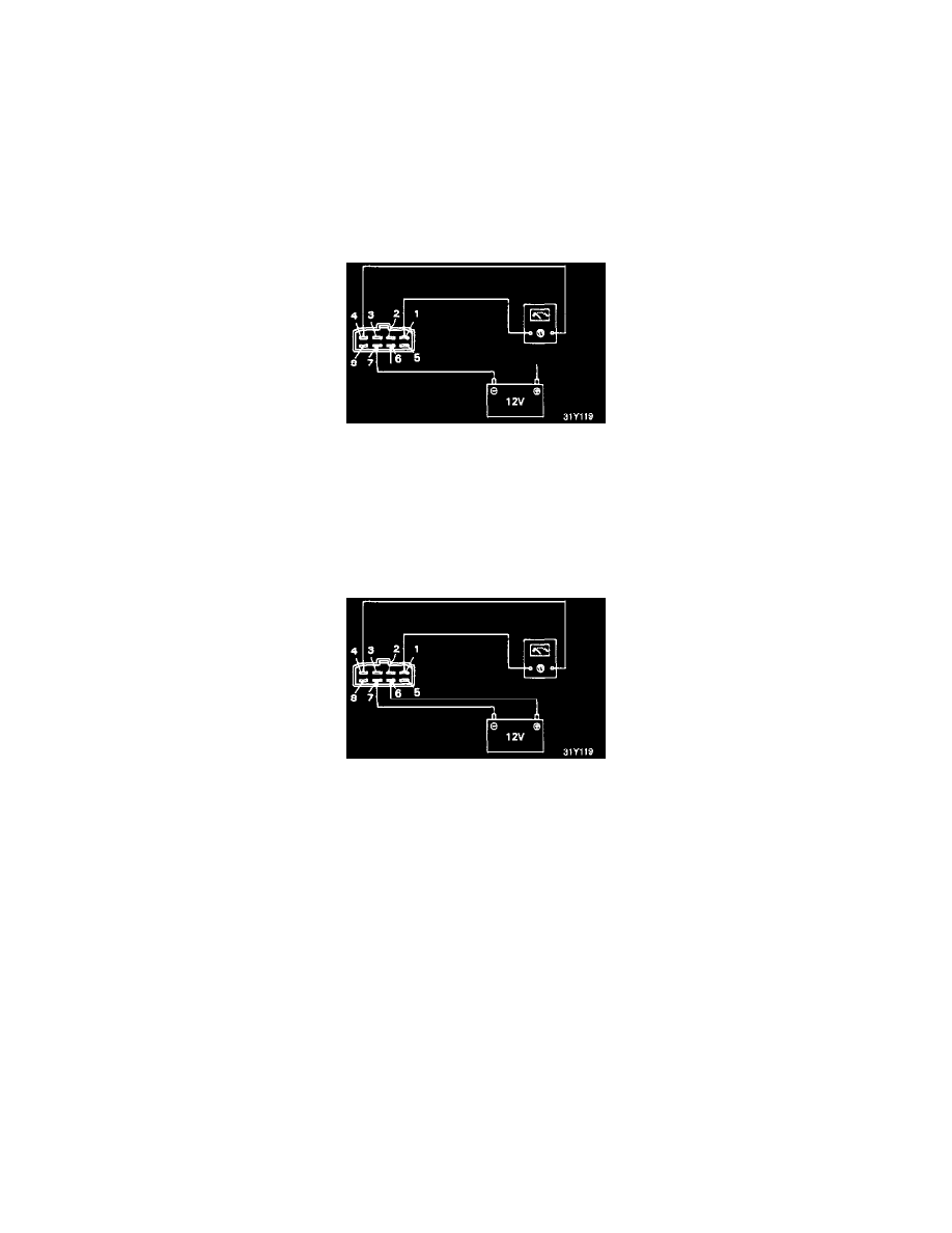
Apply positive power to terminal 6 with negative power applied to terminal 7.
Check terminals 1 and 4: should be conductive (0 ohm).
Remove power.
To test coil L3:
Check terminals 1 and 2, should be non-conductive (infinite ohm).
Check terminals 7(+) and 5(-), should be non-conductive (infinite ohm).
Check terminals 5(-) and 7(+), should be conductive (0 ohm).
Apply positive power to terminal 5 with negative power applied to terminal 7.
Check terminals 1 and 2, should be conductive (0 ohm)
Remove power.
Test between each terminal and the case: All terminals should be non-conductive (infinite ohm).
2.
If the results are not satisfactory, replace the control relay.