
Precis L4-1468cc 1.5L SOHC (1993)
not visible through notched hole of rack housing.
29. Using bearing installer, install oil seal and ball bearing to valve body.
30. Apply suitable lubricant to pinion valve assembly, then install to gear housing.
31. Using a countershaft bearing installer or equivalent, install the seal to valve body housing.
32. Install valve body assembly with the seal ring to gearbox, then the new tab washer and tie rod. Caulk tab washer end at two points to the tie rod.
33. Rotate pinion fully clockwise, then tighten new self-locking nut.
34. Apply suitable sealant to threaded section of end plug, then tighten to specifications.
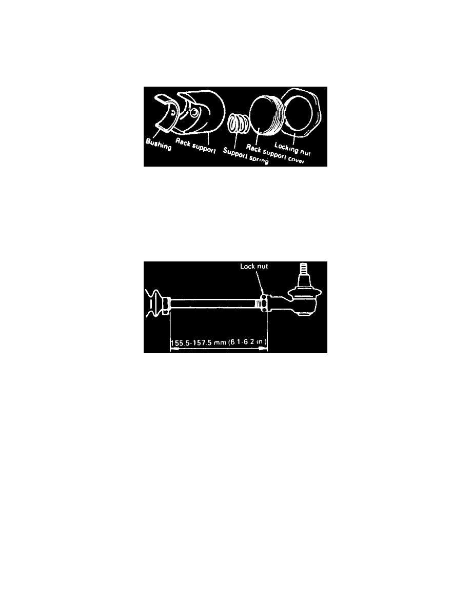
Fig. 33 Exploded View Of Rack Support
35. Stake end plug at two points using a suitable punch, then install bushing, rack support, spring, and support cover as shown, Fig. 33. Apply suitable
lubricant to threaded section of rack support prior to installation.
36. Place rack at center position, then tighten rack support cover to specifications. Loosen cover approximately 30-60°, then tighten locking nut to
specifications.
37. Tighten feed tube nut to specifications, then install mount rubber using a suitable adhesive.
38. Apply suitable lubricant to bellows fitting position of tie rod, then install new attaching band to the bellows.
39. Fill inside of dust cover with a suitable lubricant, then place dust cover into position with clip ring attached to groove at tie rod end.
Fig. 34 Tie Rod Length Adjustment
40. Install tie rods until free length of left and right rods are 6.1-6.2 inch, Fig. 34.