
Raider V6-3.7L SOHC (2006)
Fog/Driving Lamp Relay: Description and Operation
RELAY - FRONT FOG LAMP
DESCRIPTION
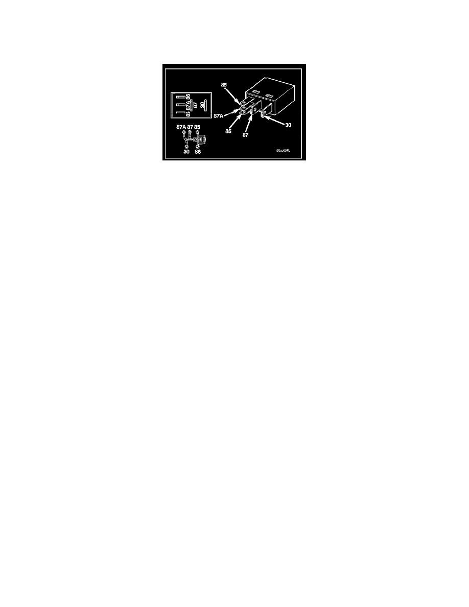
The front fog lamp relay is a conventional International Standards Organization (ISO) micro relay. Relays conforming to the ISO specifications have
common physical dimensions, current capacities, terminal patterns, and terminal functions. This relay is contained within a small, rectangular, molded
plastic housing and is connected to all of the required inputs and outputs through five integral male spade-type terminals that extend from the relay base
plate. The front fog lamp relay is located in the Power Distribution Center (PDC) in the engine compartment near the battery. Refer to the layout label on
the underside of the PDC cover for specific relay cavity assignment information. The front fog lamp relay cannot be adjusted or repaired and, if faulty or
damaged, the unit must be replaced.
OPERATION
The front fog lamp relay is an electromechanical switch that uses a low current input from the Front Control Module (FCM) (also referred to as the
Integrated Power Module/IPM) to control a high current output to the front fog lamps. Within the relay are an electromagnetic coil, a movable contact
and two fixed contact points. A resistor is connected in parallel with the coil, and helps to dissipate voltage spikes and electromagnetic interference that
can be generated as the field of the relay coil collapses. The movable common supply contact point is held against the fixed normally closed contact
point by spring pressure. When the relay coil is energized, an electromagnetic field is produced by the coil windings. This field draws the movable
contact away from the normally closed contact, and holds it against the normally open contact. When the relay coil is de-energized, spring pressure
returns the movable contact back against the normally closed contact. The inputs and outputs of the front fog lamp relay include:
-
Common Supply Terminal (30) - The common feed terminal is connected to a fused B(+) circuit at all times.
-
Coil Ground Terminal (85) - The coil ground terminal is connected to a fused B(+) circuit at all times.
-
Coil Battery Terminal (86) - The coil battery terminal is connected to a control output of the FCM through a fog lamp relay control circuit. The
FCM controls front fog lamp operation by controlling a ground path through this circuit.
-
Normally Open Terminal (87) - The normally open terminal is connected to the front fog lamps through a fog lamp relay output circuit and
provides battery voltage to the front fog lamps whenever the relay is energized.
-
Normally Closed Terminal (87A) - The normally closed terminal is not connected to any circuit in this application, but will have battery voltage
present whenever the relay is de-energized. The front fog lamp relay can be diagnosed using conventional diagnostic tools and methods. Refer to
the appropriate wiring information.