
Raider 4WD V6-3.7L SOHC (2007)
Clockspring Assembly / Spiral Cable: Adjustments
The content of this article reflects the changes identified in TSB-08-52B-001
STANDARD PROCEDURE
CLOCKSPRING CENTERING
WARNING: To avoid personal injury or death, on vehicles equipped with airbags, disable the supplemental restraint system before attempting
any steering wheel, steering column, airbag, occupant classification system, seat belt tensioner, impact sensor, or instrument panel component
diagnosis or service. Disconnect and isolate the battery negative (ground) cable, then wait two minutes for the system capacitor to discharge
before performing further diagnosis or service. This is the only sure way to disable the supplemental restraint system. Failure to take the
proper precautions could result in accidental airbag deployment.
NOTE: Before starting this procedure, be certain to turn the steering wheel until the front wheels are in the straight-ahead position.
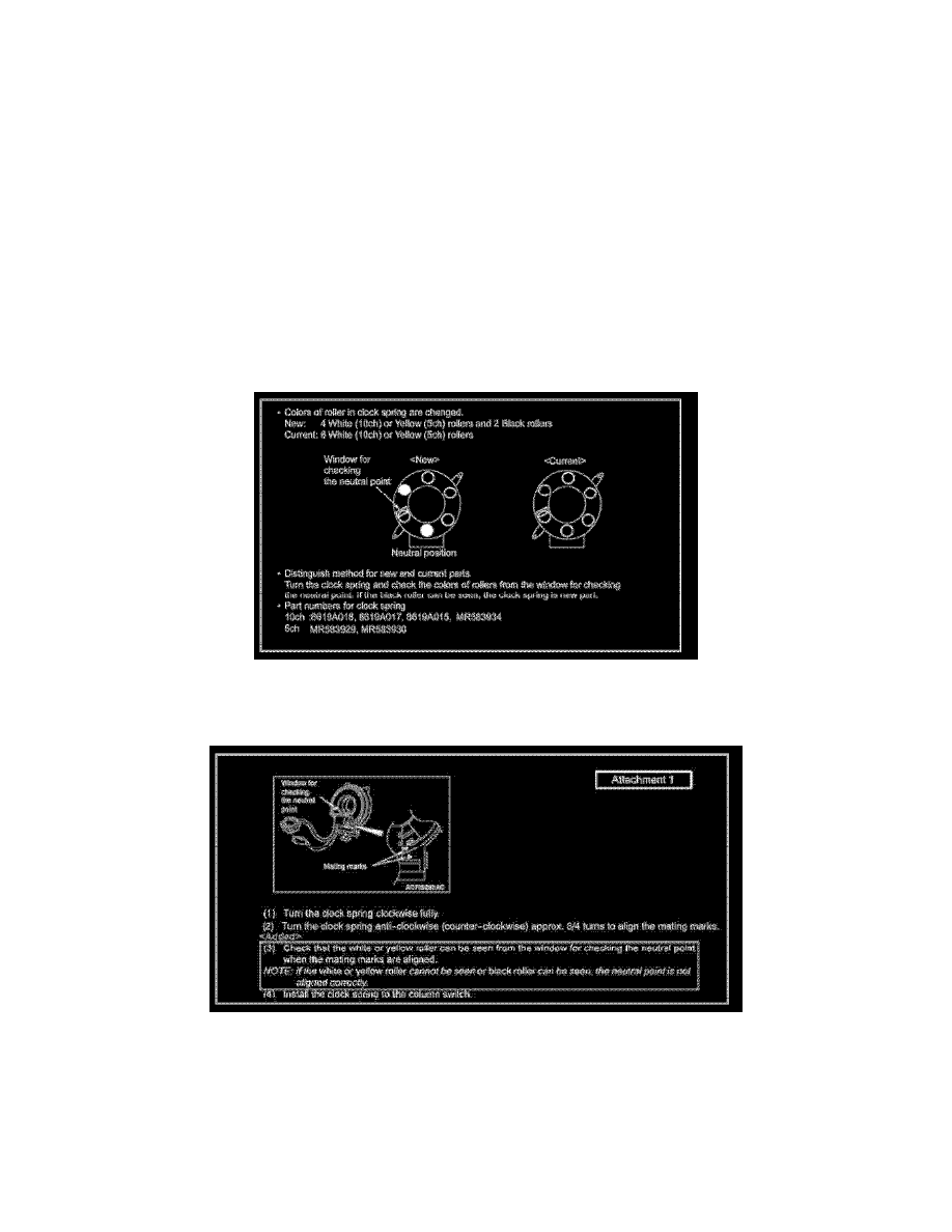
A modified clock spring has been adopted for Service Parts on affected vehicles as of September 2007. New and old style parts are interchangeable. This
TSB advises the procedures for alignment of the neutral point of the new clock spring when a part is replaced.
Parts Identification
Replacement Clockspring Alignment As Per Manual Update TSB-08-52B-001
Mating Mark Alignment
Replacement Clockspring Alignment As Per Manual Update TSB-08-52B-001 (Part 2)
1. Turn the clockspring clockwise fully.
2. Turn the clockspring anti-clockwise (counter-clockwise) approx. 3/4 turns to align the mating marks.
3. Check that the white or yellow roller can be seen from the window for checking the neutral point when the mating marks are aligned.
NOTE: If the white or yellow roller cannot be seen or black roller can be seen, the neutral point is not aligned correctly.
4. Install the clockspring to the column switch.