
Tredia L4-2.0L SOHC (1985)
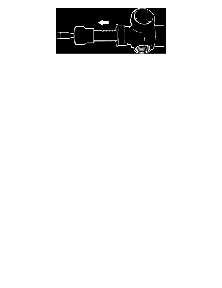
Fig. 2 Removing rack from gear housing, w/man. steer
9.
Press bearing off of pinion, then remove rack from gear housing. Remove rack in direction shown, Fig. 2, to avoid damaging the gear box
bushing.
Inspection
Check all steering gear components and repair or replace as necessary.
1.
Inspect support yoke for damage or uneven wear.
2.
Inspect yoke spring for deterioration and free length. Free length should be .46 inch on Cordia & Tredia models or .55 inch on Precis models.
3.
Inspect rubber spring for cracking or deterioration.
4.
Check mounting rubber for wear or damage.
5.
Inspect rack and pinion for damage or worn tooth surfaces.
6.
Check bearings for wear, damage, noise or uneven rotation.
7.
Inspect rack bushing for wear or damage.
8.
Inspect dust cover for cracking or damage.
Assembly
1.
Apply suitable grease to rack pinion tooth surfaces, rack bushing and needle bearings, then install rack into gear housing.
2.
Press bearing onto pinion using tool MB990783, or equivalent.
3.
Select snap ring which will minimize pinion endplay, then install snap ring on pinion and pinion into housing. Install outer snap ring to pinion.
Snap rings are available in the following sizes: .062 inch (blue), .065 inch (white) and .068 inch (yellow).
4.
Apply suitable grease to lip of oil seal, then install seal into housing.
5.
Apply suitable grease to inside of support yoke and sealant to locking nut threads.
6.
Install support yoke, cushion rubber, yoke spring, yoke plug and plug locking nut. With gear housing positioned at center of rack, torque yoke plug
to 5.7 ft. lbs. on Cordia and Tredia models or 8 ft. lbs. on Precis models. Loosen yoke plug 30°-60° and torque locknut to 36-51 ft. lbs.
7.
Install tie rod to rack and secure in place by bending new tab washer onto stepped portions of tie rod.
8.
Apply suitable grease to bellows mating surfaces, then install bellows, using new bands. Use care not to twist bellows when installing.
9.
Fill inside and lip of dust cover with suitable grease, then install dust cover and clip ring.
10.
Install right and left tie rods and adjust so that their lengths are equal. On Cordia and Tredia models, lengths should be 7.2-7.3 inches. On Precis
models, lengths should be 6.83 inch.
11.
Adjust total pinion preload as follows:
a. Measure preload while rotating pinion gear at a rate of approximately one revolution per 4-6 seconds. Preload should measure 6-11 inch lbs.
on Cordia and Tredia models or 3.6-9.6 inch lbs. on Precis models.
b. If preload is not within specifications, adjust yoke plug and recheck.
c. If preload cannot be brought within specifications by adjusting the yoke plug, inspect yoke plug, spring, cushion rubber and support yoke and
replace parts as necessary.
d. On Precis models, measure rack starting force, using a suitable tool. Rack starting force should be 11-66 lbs.
12.
On 1984 models, measure full rack stroke (lock to lock). Rack stroke should measure 5.6-5.7 inches. If not, replace gearbox assembly.
13.
On 1984 models, measure tie rod angle deflection. Deflection should be 30° in either direction. If not, replace tie rod.
14.
On 1984 models, using a spring scale, measure effort needed to move tie rod at a mid-point of the articulation range (in line with the rack). If
deflection torque measures less than 9 inch lbs., replace tie rod.
15.
On 1985-88 models, ensure tie rod swings smoothly and is not loose. Replace as required.