
405 L4-1905cc 1.9L (1989)
Radiator Cooling Fan Temperature Sensor / Switch: Description and Operation
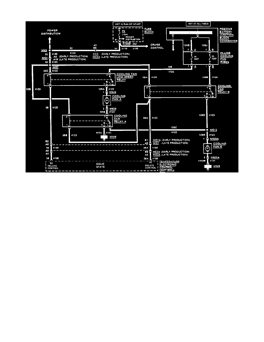
Fig. 1 Cooling Fan Wiring Circuit
When the ignition switch is in Run or Start, fuse F5 applies voltage to the cooling fan low speed relay, cooling fan relay A, and the cooling fan relay B,
Fig. 1. The positive battery junction connector applies voltage at all time to the cooling fan low speed relay and the cooling fan relay B.
The temperature electronic control unit receives input from the coolant temperature sensor and the A/C circuit. With these inputs, the temperature
electronic control unit determines which cooling fan should be on.
The cooling fans are turned on by the temperature electronic control unit providing ground for the relay or relays. The contacts will close and voltage
will be applied to the cooling fan. When only cooling fan A is on, it receives ground through the cooling fan B.