
Prowler V6-3.5L VIN G (1999)
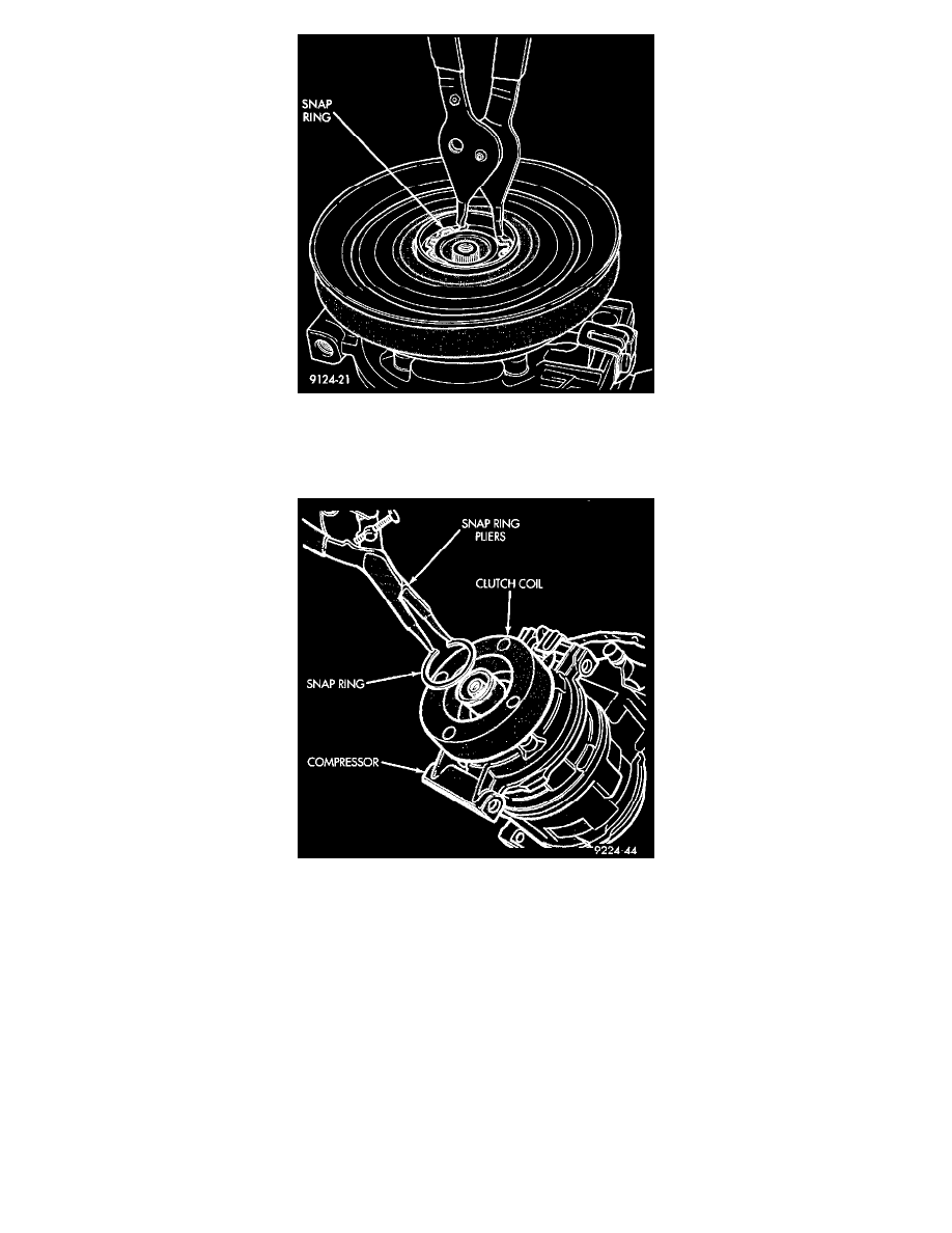
Fig 16 Removing Pulley Snap Ring
4. Remove pulley retaining snap ring with Snap Ring Pliers (C-4574), and slide pulley assembly off of compressor.
5. Remove coil wire bracket/ground clip screw and wire harness.
Fig 17 Clutch Coil Snap Ring
6. Remove snap ring retaining field coil onto compressor housing. Slide field coil off of compressor housing.
7. Examine frictional faces of the clutch pulley and front plate for wear. The pulley and front plate should be replaced if there is excessive wear or
scoring. If the friction surfaces are oily, inspect the shaft nose area of the compressor for oil and remove the felt from the front cover. If the
compressor felt is saturated with oil, the shaft seal is leaking and will have to be replaced.
8. Check bearing for roughness or excessive leakage of grease. Replace bearing as required.
INSPECTION
Examine frictional faces of the rotor-pulley and armature plate for wear. The pulley and plate should be replaced if there is excessive wear or
scoring. If the friction surfaces are oily, inspect the shaft nose area of the compressor for excess oil. If excess oil is present, the shaft seal is leaking
and the compressor must be replaced.
Check pulley hub bearing for roughness or excessive grease leakage. Check for bearing grease contamination on armature plate faces.
CAUTION: The pulley and clutch plate were mated at the factory by a burnishing operation. No attempt should be made to separately replace either
part. This will result in clutch slippage due to insufficient contact area.