
Prowler V6-3.5L VIN G (1999)
INSTALLATION
1. Align pin in back of field coil with hole in compressor end housing, and position field coil into place. Make sure that lead wires are properly
routed, and fasten the diode and coil wire bracket with retaining screw.
2. Install field coil retaining snap ring with Snap Ring Pliers (C- 4574). Press snap ring to make sure it is properly seated in the groove.
NOTE: The bevel side of the snap ring must be out- ward. Also both eyelets must be to the right or left of the pin on the compressor.
CAUTION: If snap ring is not fully seated it will vibrate out, resulting in a clutch failure and severe damage to the front face of the compressor.
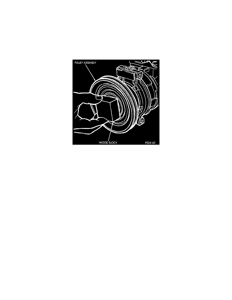
CAUTION: Do not mar the pulley frictional surface.
Fig 18 Installing Pulley Assembly
3. Install pulley assembly to compressor. If necessary, tap gently with a block of wood on the friction surface.
4. Install pulley assembly retaining snap ring (bevel side outward) with Snap Ring Pliers (C-4574). Press the snap ring to make sure it is properly
seated in the groove.
NOTE: The bevel side of the snap ring must be facing outward.
5. If the original front plate assembly and pulley assembly are to be reused, the old shim(s) can be used. If not, place a trial stack of shims, 2.54 mm
(0.10 in.) thick, on the shaft against the shoulder.
6. Install front plate assembly onto shaft.
7. If installing a new front plate and/or pulley assembly, the gap between front plate and pulley face must be checked. Use the following procedure:
a. Attach a dial indicator to front plate so that movement of the plate can be measured.
b. With the dial indicator zeroed on the front plate, energize the clutch and record the amount of movement.
c. The readings should be 0.35 to 0.65 mm (0.014 to 0.026 in.). If proper reading is not obtained, add or subtract shims until desired reading is
obtained.
8. Install compressor shaft bolt.
-
Tighten to 17.5 +/- 2 Nm (155 +/- 20 in. lbs.).
NOTE: Shims may compress after tightening shaft nut. Check air gap in four or more places to verify if air gap is still correct. Spin pulley for final
check.
CLUTCH BREAK-IN
After new clutch installation, cycle the A/C clutch 20 times (5 seconds ON and 5 seconds OFF). During this procedure, set the system to the A/C
mode, engine rpm at 1,500 to 2,000, and high blower speed. This procedure (burnishing) will seat the opposing friction surfaces and provide a
higher clutch torque capability.