
Firebird V8-305 5.0L (1982)
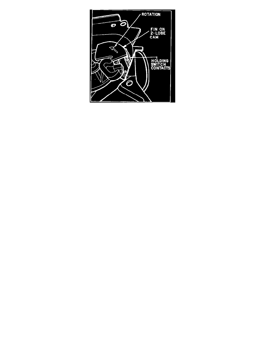
Fig. 8 Pulse wiper system holding switch. Compound wound round windshield wiper motor
Operation:
Models with pulse wiper use a motor similar to the one used on standard systems, but with modifications to provide a delay wipe mode. The multiplex
system, while similar to earlier pulse wipe systems, uses an integrated circuit timer and the voltage feed to the wiper switch has been eliminated. In
addition to standard wiper system components, the multiplex system uses a variable resistor in the wiper switch, a pulse relay and holding switch
mounted in the washer pump, and a timer circuit. The timer, consisting of a capacitor and integrated circuit, is mounted on a circuit board in the washer
pump or contained in a separate module.
The gear box relay functions in a similar manner on both standard and multiplex systems. However, on pulse systems the gear box relay supplies voltage
to the pulse relay, current to the motor windings is controlled by the pulse relay, and voltage is supplied to the timer circuit from motor terminal 2. In all
switch positions except delay, the gear box relay, pulse relay and timer capacitor circuits are completed directly to ground through the wiper switch. This
deactivates the timer circuit and allows the motor to operate as outlined in ``Standard (Non-Pulse) Wiper Operation.''
Placing wiper switch in delay position grounds gear box relay terminals 1 (relay) and 3 (shunt field), and the timer capacitor is partially grounded
through the variable resistor, allowing it to charge at a controlled rate. When the timer capacitor is fully charged it activates the integrated circuit. The
integrated circuit completes the pulse relay ground circuit, and current flows through the motor windings.
As the motor begins to operate, holding switch contacts close, the capacitor discharges partially, and the pulse relay ground is maintained by the holding
switch. As wipers complete their cycle, a fin on the washer pump drive cam opens the holding switch, Fig. 8, wipers stop and the timer capacitor begins
to recharge. This cycle repeats as long as wiper switch is in delay position. Delay between wipes is determined by varying resistance between the timer
capacitor and ground.