
Firebird V8-305 5.0L VIN E TBI (1989)
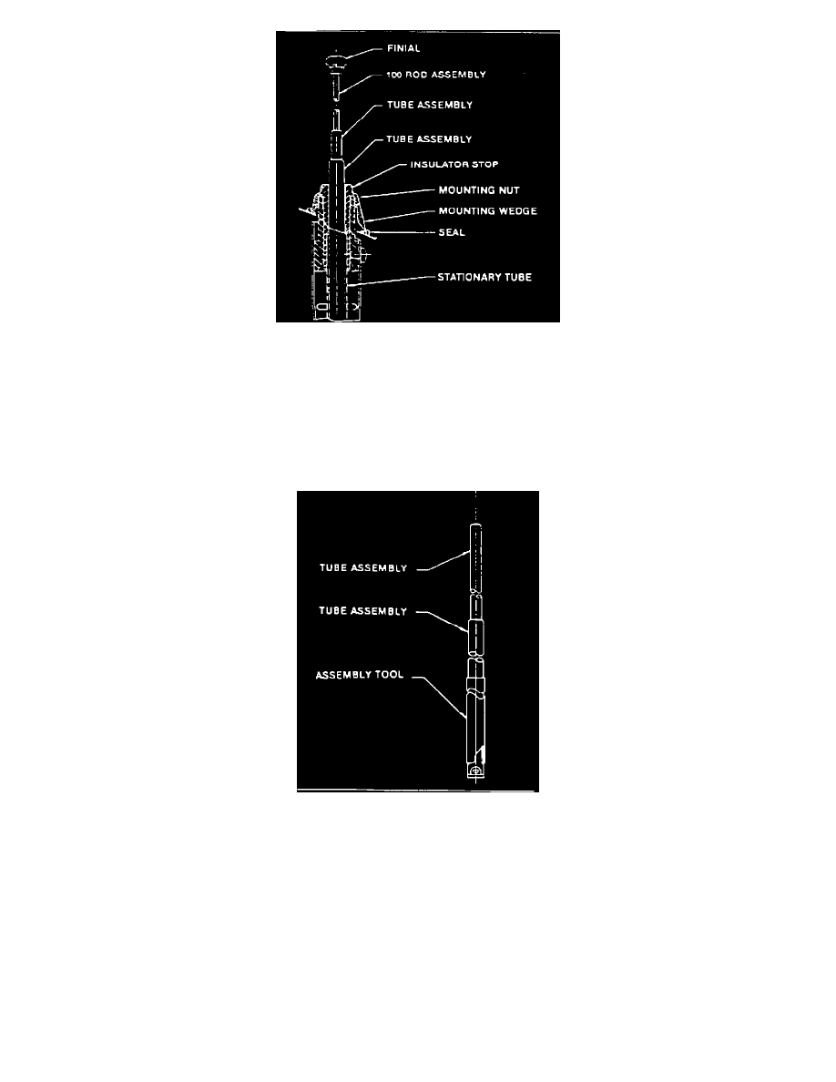
FIGURE 3 - REAR MOUNTED ANTENNA
C.
Rear mounted (Figure 3). Remove insulator stop using a 14 mm deep well, 12 point socket.
4.
Remove finial using a wrench or suitable tool on flats of finial. Keep the 100 rod assembly from turning by gripping rod with pliers padded with
cloth or rubber to prevent damage to rod surface. Do not bend 100 rod.
5.
Using long nose pliers or fingers, remove the tube assemblies from the antenna, sliding them over the 100 rod assembly.
NOTE:
Antennas may have two or three tube assemblies.
FIGURE 4 - ASSEMBLY TUBE INSTALLED
MAST SECTION INSTALLATION
1.
Before assembling the new mast, lubricate the contactor with lubrication supplied.
2.
Slide the assembly tool over the contactor to compress its fingers (Figure 4). Slide the mast assemblies over the 100 rod and into the stationary
tube, past the contactor fingers.
Remove the assembly tool, then bottom the mast in the stationary tube. Make sure the threaded top of the 100 rod is above the top of the first tube.
3.
Reinstall (where applicable) seal, mounting wedge, mounting nut, insulator stop and finial in the reverse order of removal instructions.
4.
Reconnect power.