
911 Carrera 2 Cabriolet F6-3600cc 3.6L SOHC (1992)
6.3 -
Reassemble plug M2 and reconnect into the control unit.
7
-
Route the additional 0.5 mm red wire and green / white wire along the under dash and up to the area of the oil pressure/oil temp. gauge. Route the
additional wires along the existing harness and secure using cable ties.
7.1 -
Pull the oil pressure / oil temperature gauge from the dash panel.
7.2 -
Pull the 0.5 mm red / yellow wire connector from the cabrio top control light.
7.3 -
Join the additional 0.5 mm red wire to the existing 0.5 mm red / yellow wire and solder (see wiring diagram 7.3). Insulate the connection with
electrical tape and reconnect onto the Cabrio top control light terminal.
7.4 -
Pull the additional green / white wire through the flat connector housing (999 652 199 40) and crimp the flat male connector (N 017 242 11) onto
the end of the wire. Insert the flat connector into the flat connector housing. Connect the additional green / white wire onto terminal G of the oil
pressure / oil temperature gauge (see wiring Diagram 7.4).
7.5 -
Pull the speedometer from the dash panel. Remove the red / yellow wire on terminal + (plus). Cut off the flat connector. Insulate and tape this
wire to the back of the harness.
7.6 -
Reinstall the speedometer and oil pressure/oil temperature gauges.
8
-
Route the additional brown / white wire along the center tunnel to the area of the shift coupler cover.
8.1 -
Remove the shift coupler cover. Locate the wiring harness inside the tunnel and very carefully cut the harness open with a knife.
8.2 -
Locate the 0.5 mm brown / white wire (from the hand brake switch) in the harness. Connect the additional 0.5 mm brown / white wire to the
existing brown/white wire in the harness and solder. Insulate the connection with electrical tape. Approximately 2 cm from the solder connection
and toward the rear of the vehicle, cut the brown / white wire in the harness and install the diode (911 617 106 01). Pay attention to the correct
installation position of the diode (see wiring diagram 8.2, page 5). Solder the diode into place and insulate the connections with electrical tape.
Close the harness using electrical tape and reinstall the shift coupler cover.
9
-
Reinstall the passenger's foot board and related parts. Reconnect the battery, reset the vehicle clock, and recode the radio.
10 -
Function test the system.
10.1 - Pull the hand brake lever up.
10.2 - Place the ignition key in position 2 (ignition on or engine running).
10.3 - Open and close the Cabrio top using the control switch.
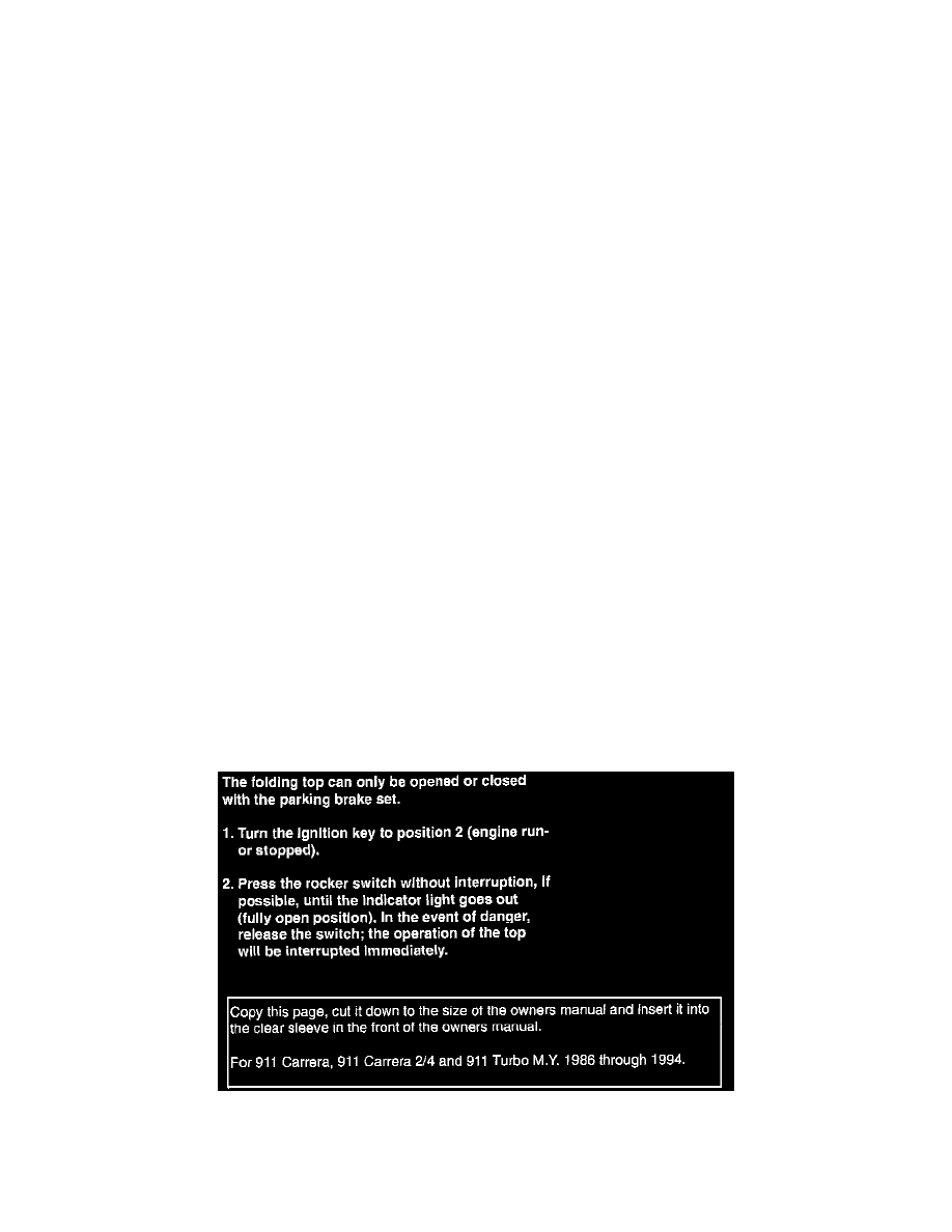
11 -
Ensure that the vehicle owner is aware of the change in operating instructions for the Cabrio top.The changed operating instructions for the
owner's manual are found in this bulletin. Copy the page, cut it down to the size of the owner's manual, and insert it into the clear sleeve in the
front of the owner's manual.