
Joints and joint faces
- Make
- Rover
- Model
- 200 Workshop Manual
- Year
- 1995–1999
- Section
- General precautions and fitting instructions › Joints and joint faces
Joints and joint faces
Fit joints dry unless otherwise specified in this Manual.
If gaskets and/or jointing compound is recommended for use; remove all traces of old jointing material prior to reassembly. Do not use a tool which will damage the joint faces and smooth out any scratches or burrs on the joint faces using an oil stone. Do not allow dirt or jointing material to enter any tapped holes.
Prior to reassembly, blow through any pipes, channels or crevices with compressed air.
Screw threads
Metric threads to ISO standards are used.
Damaged nuts, bolts and screws must always be discarded.
Cleaning up damaged threads with a die or tap impairs the strength and closeness of fit of the threads and is not recommended.
Castellated nuts must not be slackened back to accept a split-pin, except in those recommended cases when this forms part of an adjustment.
Do not allow oil or grease to enter blind threaded holes. The hydraulic action on screwing in the bolt or stud could split the housing.
Always tighten a nut or bolt to the recommended torque figure. Damaged or corroded threads can affect the torque reading.
To check or re-tighten a bolt or screw to a specified torque figure, first slacken a quarter of a turn, then retighten to the correct torque figure.
Bolt identification
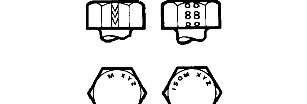
An ISO metric bolt or screw made of steel and larger than 6 mm in diameter can be identified by either of the symbols ISO M or M embossed or indented on top of the head.
In addition to marks to identify the manufacturer, the head is also marked with symbols to indicate the strength grade, e.g. 8.8; 10.9; 12.9; 14.9. As an alternative, some bolts and screws have the M and strength grade symbol on the flats of the hexagon.
Parts & tools for this job For 1995 Rover 200
- TOOLTorque wrenchSearch: 3/8 inch torque wrench
- TOOLSocket setSearch: socket set metric
- BOOKHaynes manualSearch: Haynes manual Rover 200
Links open Amazon search results in a new tab. As an Amazon Associate I earn from qualifying purchases.