
Restraint systems (Component location): Description and operation
- Make
- Rover
- Model
- 200 Workshop Manual
- Year
- 1995–1999
- Section
- Description and operation › Component location
Restraint systemsComponent location
COMPONENT LOCATION
NOTE: LHD type is symmetrical to RHD type.
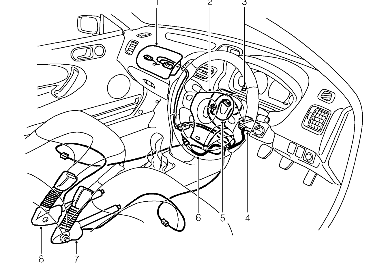
- Passenger’s airbag module *
- Driver’s airbag module *
- SRS warning lamp
- Diagnostic control unit *
- Rotary coupler *
- SRS harness (YELLOW) *
* Components to be renewed following system deployment.
NOTE: Following deployment of the Supplementary Restraint System (SRS) within the vehicle, under any circumstances, all system components including the yellow harnesses MUST be replaced.
Parts & tools for this job For 1995 Rover 200
- TOOLOBD2 scanner with SRSSearch: OBD2 scanner ABS SRS
- TOOLTrim removal tool kitSearch: trim removal tool kit
Links open Amazon search results in a new tab. As an Amazon Associate I earn from qualifying purchases.