
Electronic control units (Information)
- Make
- Rover
- Model
- 400 Body Repair Manual
- Year
- 1995–2000
- Section
- Component locations › Electronic control units
ELECTRONIC CONTROL UNITS
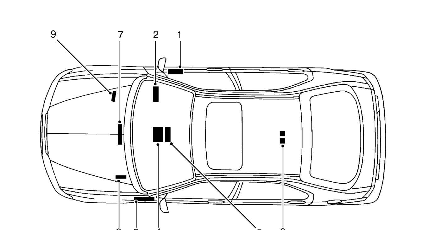
- Window lift ECU
- Integrated Control Unit
- PGM-Fi ECM - 416 automatic
- SRS relay
- Central door locking and anti-theft alarm ECU
The electronic control units fitted to Rover vehicles make it advisable to follow suitable precautions prior to carrying out welding repair operations. Harsh conditions of heat and vibration may be generated during these operations which could cause damage to the units. See GENERAL INFORMATION, Electrical precautions.
In particular, it is essential to follow the appropriate precautions when disconnecting or removing the SRS diagnostic and control unit. See RESTRAINT SYSTEMS, Precautions.
- Sunroof relays
- MEMS ECM
- ABS ECU - except 416 automatics
- ABS ECU - 416 automatics
Equipment - Prior to commencing any test procedure on the vehicle, ensure that the relevant test equipment is working correctly and any harness or connectors are in good condition. This particularly applies to electronic control units.
Parts & tools for this job For 1995 Rover 400
- TOOLTorque wrenchSearch: 3/8 inch torque wrench
- TOOLSocket setSearch: socket set metric
- BOOKHaynes manualSearch: Haynes manual Rover 400
Links open Amazon search results in a new tab. As an Amazon Associate I earn from qualifying purchases.