
Engine management system
- Make
- Rover
- Model
- 400 Circuit Diagrams
- Year
- 1997/5 model year on
- Section
- Engine management system › Engine management system
Engine management systemEngine management system
ENGINE MANAGEMENT SYSTEM
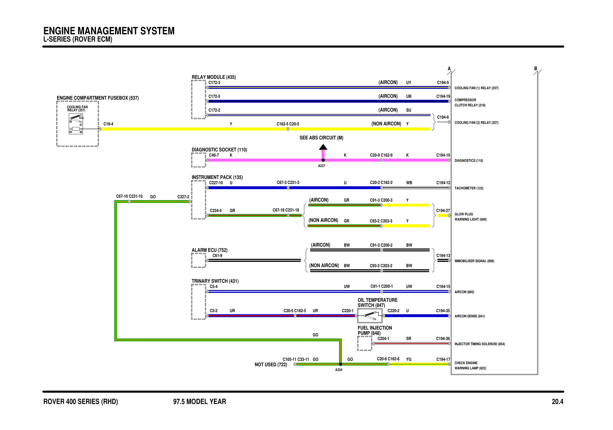
Components on this diagram
- AIRCON (860)
- AIRCON SENSE (841)
- ALARM ECU (752)
- CHECK ENGINE WARNING LAMP (622)
- COMPRESSOR CLUTCH RELAY (218)
- DIAGNOSTIC SOCKET (110)
- DIAGNOSTICS (110)
- ENGINE COMPARTMENT FUSEBOX (537)
- FUEL INJECTION PUMP (848)
- GLOW PLUG WARNING LIGHT (609)
- IMMOBILISER SIGNAL (899)
- INJECTOR TIMING SOLENOID (854)
- INSTRUMENT PACK (135)
- NOT USED (722)
- OIL TEMPERATURE SWITCH (847)
- RELAY (257)
- RELAY MODULE (435)
- TACHOMETER (123)
- TRINARY SWITCH (431)
Parts & tools for this job For 1997 Rover 400
- PARTEngine gasket setSearch: Rover 400 1997 engine gasket set
- TOOLTorque wrenchSearch: 3/8 inch torque wrench
- TOOLFeeler gauge setSearch: feeler gauge set
Links open Amazon search results in a new tab. As an Amazon Associate I earn from qualifying purchases.