
Interior illumination
- Make
- Rover
- Model
- 400 Circuit Diagrams
- Year
- 1997/5 model year on
- Section
- Interior illumination › Interior illumination
Interior illuminationInterior illumination
INTERIOR ILLUMINATION
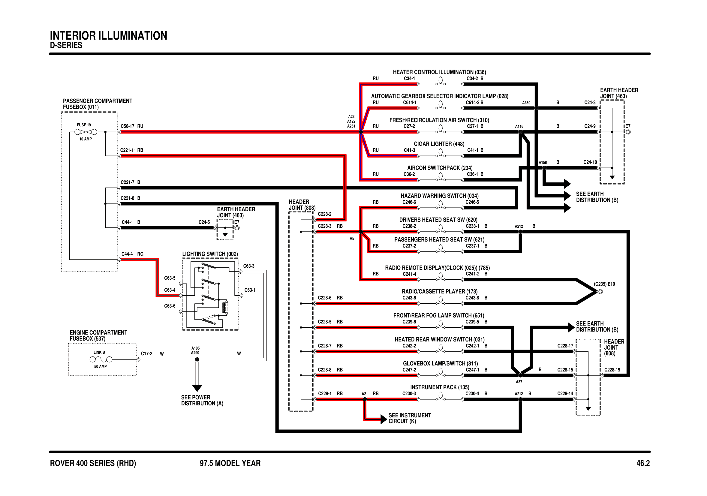
Components on this diagram
- AIRCON SWITCHPACK (234)
- AUTOMATIC GEARBOX SELECTOR INDICATOR LAMP (028)
- CIGAR LIGHTER (448)
- DRIVERS HEATED SEAT SW (620)
- EARTH HEADER JOINT (463)
- ENGINE COMPARTMENT FUSEBOX (537)
- FRESH/RECIRCULATION AIR SWITCH (310)
- FRONT/REAR FOG LAMP SWITCH (651)
- GLOVEBOX LAMP/SWITCH (811)
- HAZARD WARNING SWITCH (034)
- HEADER JOINT (808)
- HEATED REAR WINDOW SWITCH (031)
- HEATER CONTROL ILLUMINATION (036)
- INSTRUMENT PACK (135)
- LIGHTING SWITCH (002)
- PASSENGER COMPARTMENT FUSEBOX (011)
- PASSENGERS HEATED SEAT SW (621)
- RADIO/CASSETTE PLAYER (173)
Parts & tools for this job For 1997 Rover 400
- TOOLTorque wrenchSearch: 3/8 inch torque wrench
- TOOLSocket setSearch: socket set metric
- BOOKHaynes manualSearch: Haynes manual Rover 400
Links open Amazon search results in a new tab. As an Amazon Associate I earn from qualifying purchases.