
Power distribution
- Make
- Rover
- Model
- 400 Circuit Diagrams
- Year
- 1997/5 model year on
- Section
- Power distribution › Power distribution
Power distributionPower distribution
POWER DISTRIBUTION
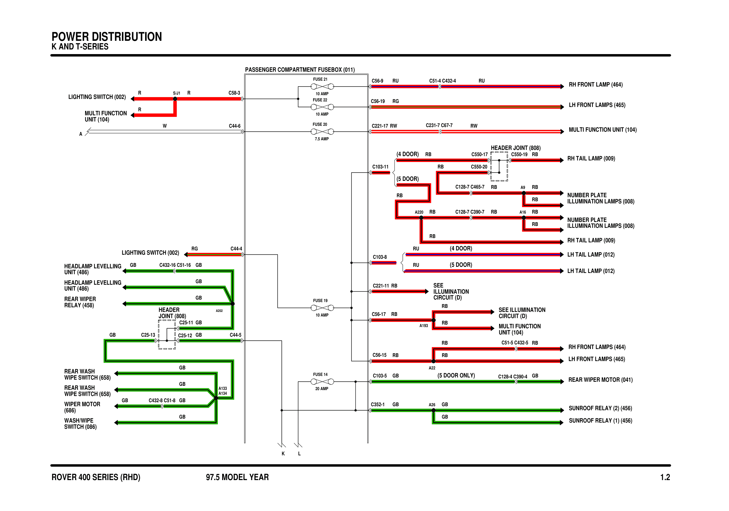
Components on this diagram
- HEADER JOINT (808)
- HEADLAMP LEVELLING UNIT (486)
- LH FRONT LAMPS (465)
- LH TAIL LAMP (012)
- LIGHTING SWITCH (002)
- MULTI FUNCTION UNIT (104)
- NUMBER PLATE ILLUMINATION LAMPS (008)
- PASSENGER COMPARTMENT FUSEBOX (011)
- REAR WASH WIPE SWITCH (658)
- REAR WIPER MOTOR (041)
- REAR WIPER RELAY (458)
- RH FRONT LAMP (464)
- RH FRONT LAMPS (464)
- RH TAIL LAMP (009)
- WASH/WIPE SWITCH (086)
- WIPER MOTOR (686)
Parts & tools for this job For 1997 Rover 400
- TOOLTorque wrenchSearch: 3/8 inch torque wrench
- TOOLSocket setSearch: socket set metric
- BOOKHaynes manualSearch: Haynes manual Rover 400
Links open Amazon search results in a new tab. As an Amazon Associate I earn from qualifying purchases.