
Workshop Manuals Factory service & repair Rover
01 Introduction02 Engine management system03 Fuel pump and gauge04 Air conditioning and cooling fans05 Wipers and washers06 Instruments07 Power distribution08 Earth distribution09 Anti-theft alarm and central door locking10 Windows11 Sunroof12 Mirrors13 Diagnostic14 Charging and starting15 Cruise control16 Anti-lock brakes (ABS)17 SRS (DRIVER only airbag)18 Seat belt warning / catalyst overheat19 Heater blower20 Heated rear window21 Exterior lamps22 Indicators and hazards23 Interior lamps24 Interior illumination25 Horns26 Cigar lighter27 In-car entertainment
Rover 400 Circuit Diagrams (1997.5 model year on)17 · SRS (DRIVER only airbag)
17 · Body & interior

SRS

Make
Rover
Model
400 Circuit Diagrams
Year
1997/5 model year on
Section
SRS › SRS
SRS (DRIVER only airbag)SRS

SRS
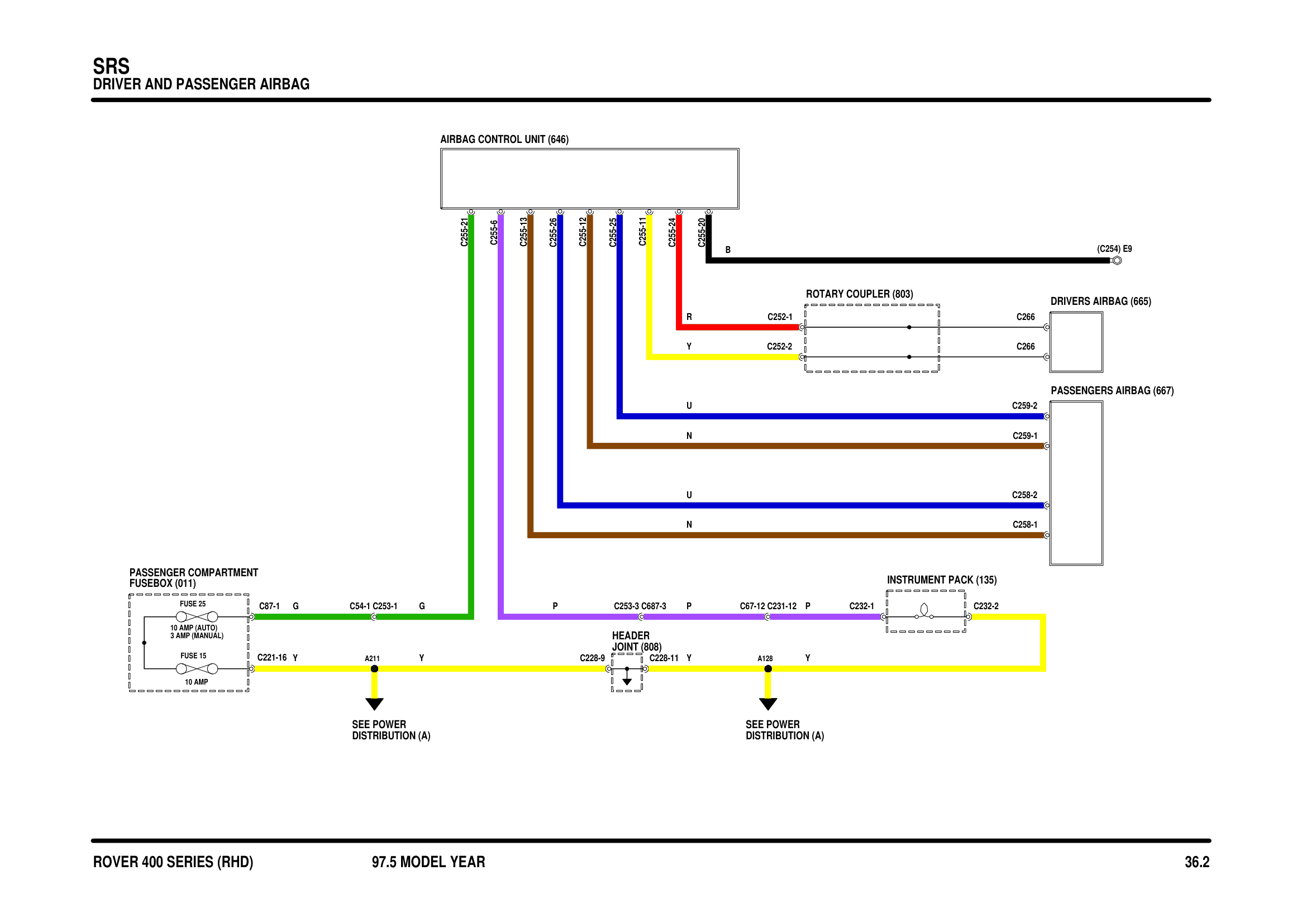
Srs circuit diagram

Components on this diagram

  • AIRBAG CONTROL UNIT (646)
  • DRIVERS AIRBAG (665)
  • HEADER JOINT (808)
  • INSTRUMENT PACK (135)
  • PASSENGER COMPARTMENT FUSEBOX (011)
  • PASSENGERS AIRBAG (667)
  • ROTARY COUPLER (803)

Parts & tools for this job For 1997 Rover 400

Links open Amazon search results in a new tab. As an Amazon Associate I earn from qualifying purchases.