
Heating & ventilation (Operation): Description and operation
- Make
- Rover
- Model
- 400 Workshop Manual
- Year
- 1995–2000
- Section
- Description and operation › Operation
OPERATION
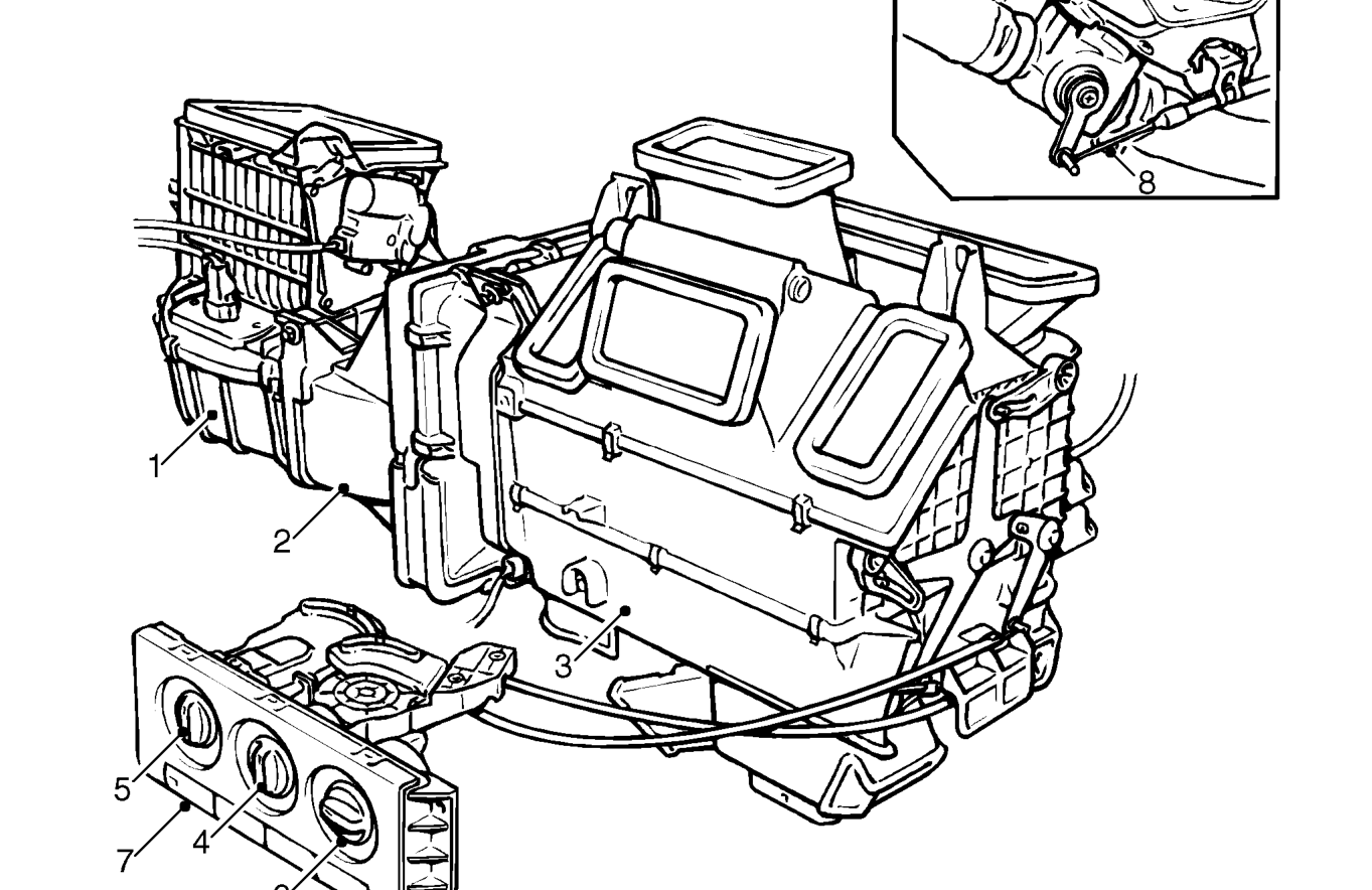
Air, drawn through the intake below the windscreen, passes through the blower unit (1), heater duct (2) and heater unit (3) to enter the interior of the car.
When the temperature control (4) is rotated towards the heated air position it opens a water valve (8) in the engine cooling system allowing hot water from the engine to circulate through the heater matrix. Rotation of the temperature control (4) also adjusts the position of the blend flap in the heater unit to direct all, or a proportion of, the intake air through the heater matrix to be heated before entering the car interior.
The distribution of air entering the car through the heater is dependent on the positions of distribution flaps inside the heater unit. The distribution flaps are adjusted by rotation of the distribution control (5) to direct the air in various proportions to the vents at face level, foot level, windscreen and front doors.
When the blower switch (6) is switched off, the volume of air entering the blower unit depends on the ram effect of the car’s forward motion. Four fan speeds are also available on the switch (6) to supplement the ram effect.
The air supply control (7) provides the facility to recirculate air inside the car in conditions when it is desirable not to draw in outside air. The control (7) operates a recirculation motor in the blower unit (1).
Operation of the thumbwheel in a side face level vent will provide unheated, unblown air from that vent regardless of the position of the distribution control (5).
Parts & tools for this job For 1995 Rover 400
- TOOLA/C manifold gauge setSearch: AC manifold gauge set
- TOOLUV leak detection kitSearch: AC UV leak detection kit
- PARTCabin filterSearch: Rover 400 1995 cabin filter
Links open Amazon search results in a new tab. As an Amazon Associate I earn from qualifying purchases.