
Instrument pack components - exploded view (Instruments)
- Make
- Rover
- Model
- 400 Workshop Manual
- Year
- 1995–2000
- Section
- Description and operation › Instrument pack components - exploded view
InstrumentsInstrument pack components - exploded view
INSTRUMENT PACK COMPONENTS - EXPLODED VIEW
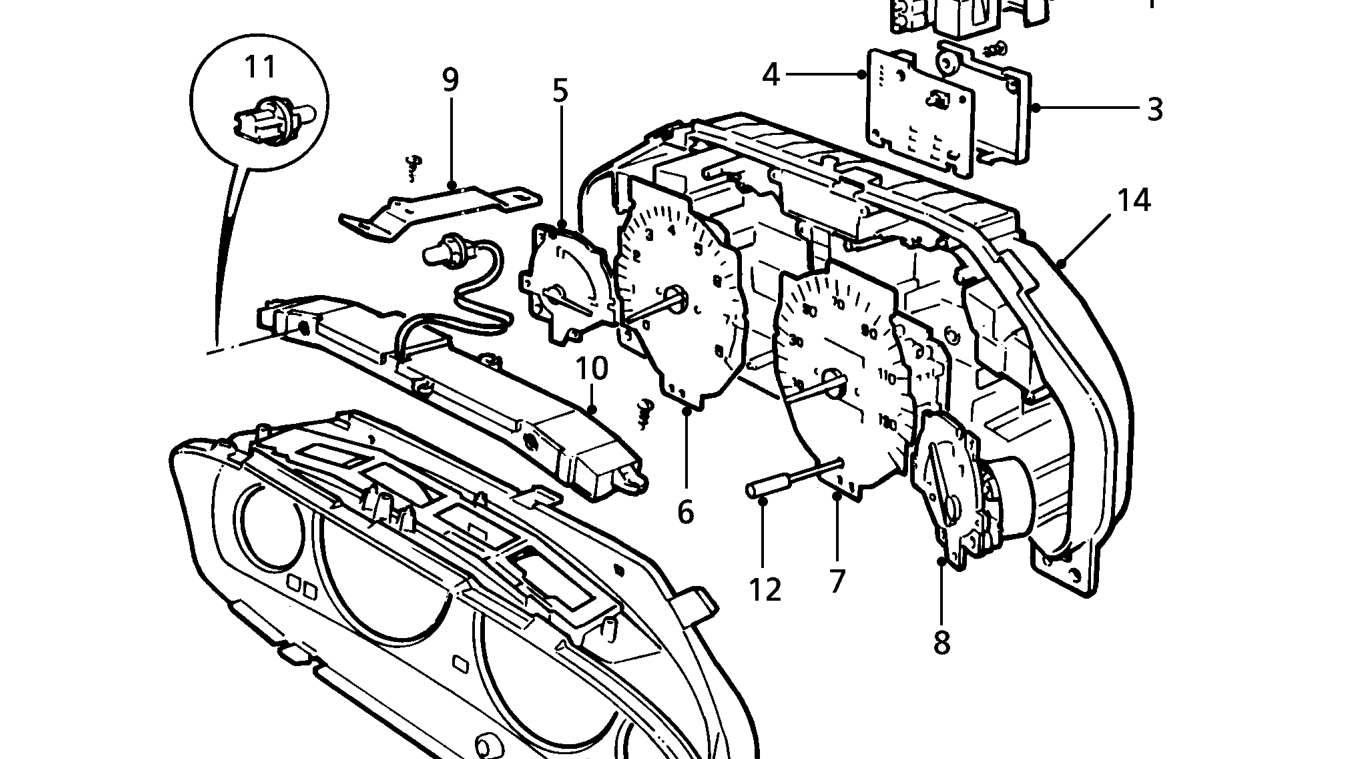
- Circuit board cover - automatic transmission indicator
- Automatic transmission indicator
- Circuit board cover - SRS indicator - D Series
- SRS indicator - D Series
- Coolant temperature gauge
- Tachometer
- Speedometer
- Fuel gauge
- Support bracket
- Panel illumination cover and printed circuit
- Panel front illumination bulbs
- Control knob - trip distance
- Instrument pack and faceplate
- Instrument pack housing
Parts & tools for this job For 1995 Rover 400
- TOOLTorque wrenchSearch: 3/8 inch torque wrench
- TOOLSocket setSearch: socket set metric
- BOOKHaynes manualSearch: Haynes manual Rover 400
Links open Amazon search results in a new tab. As an Amazon Associate I earn from qualifying purchases.