
Clutch (Clutch components): Description and operation
- Make
- Rover
- Model
- 600 620 Diesel Repair Manual Supplement
- Year
- 1995–1999
- Section
- Description and operation › Clutch components
ClutchClutch components · page 1 of 2
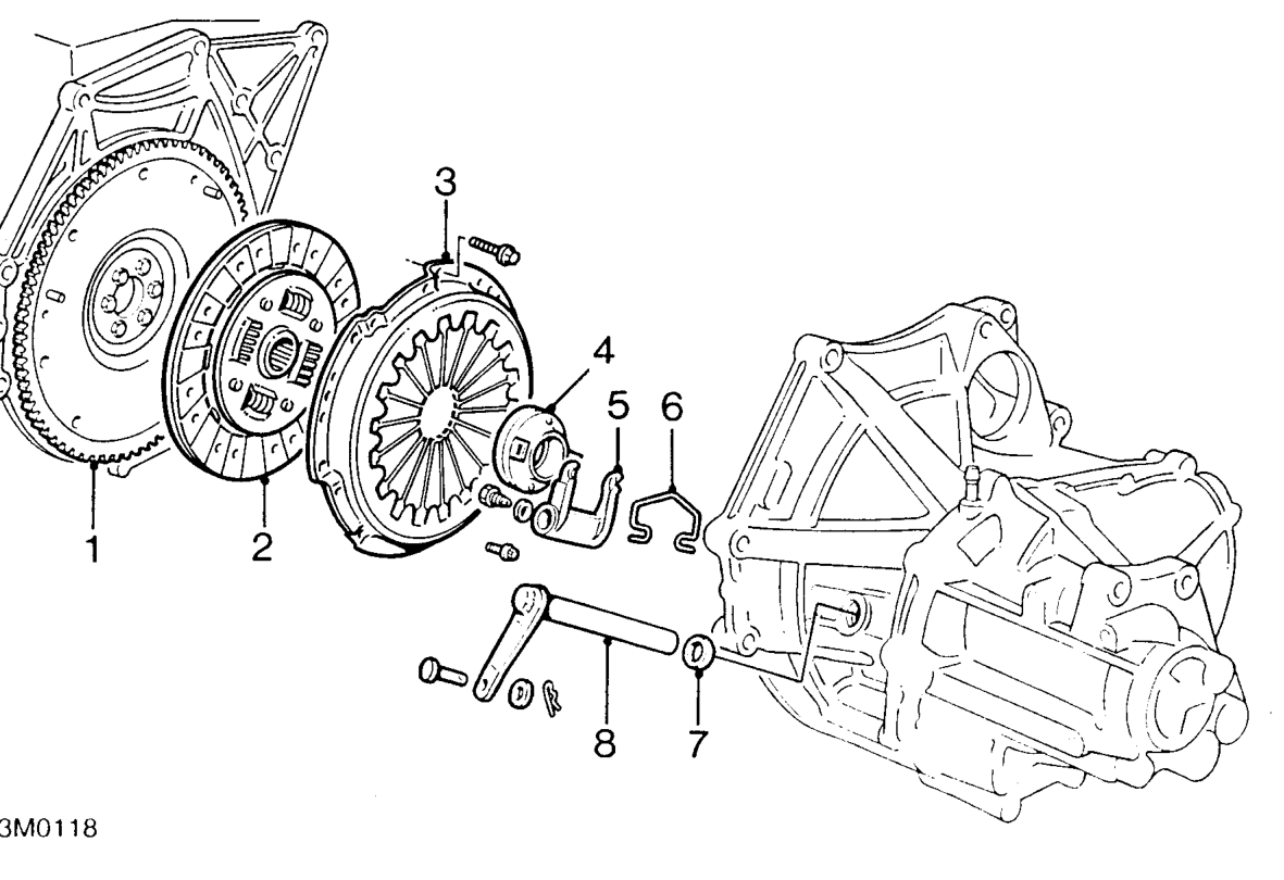
CLUTCH COMPONENTS
- Flywheel
- Clutch plate
- Pressure plate
- Release bearing
- Release fork
- Release fork spring
- Release shaft oil seal
- Release shaft
OPERATION
When the clutch pedal is depressed, fluid is pumped from the master cylinder under pressure to the slave cylinder piston which applies pressure directly to the release arm. The release shaft rotates and moves the release fork which presses the release bearing against the cluch diaphragm fingers which deflect, removing pressure from the clutch plate to disengage the clutch.
When pressure is released from the clutch pedal, the diaphragm fingers push the release bearing back and force the clutch plate under spring pressure against the flywheel.
Parts & tools for this job For 1995 Rover 600
- PARTClutch kitSearch: Rover 600 1995 clutch kit
- TOOLClutch alignment toolSearch: clutch alignment tool
- FLUIDGear oilSearch: Rover 600 manual gearbox oil
Links open Amazon search results in a new tab. As an Amazon Associate I earn from qualifying purchases.