
Modular engine management system - MPi (Ignition components): Description and operation
- Make
- Rover
- Model
- Coupé, Cabriolet & Tourer 200/400 Coupé, Cabriolet & Tourer Workshop Manual
- Section
- Description and operation › Ignition components
Ignition components
Ignition coil
Though similar in appearance to coils used in conventional ignition systems, the coil used in programmed ignition installations has a lower primary winding resistance (0.71 to 0.81 ohms at 20°C 68°F) than it's conventional counterpart. This allows the full H.t output to be reached faster and so makes the coil operation more consistent throughout the engine speed range.
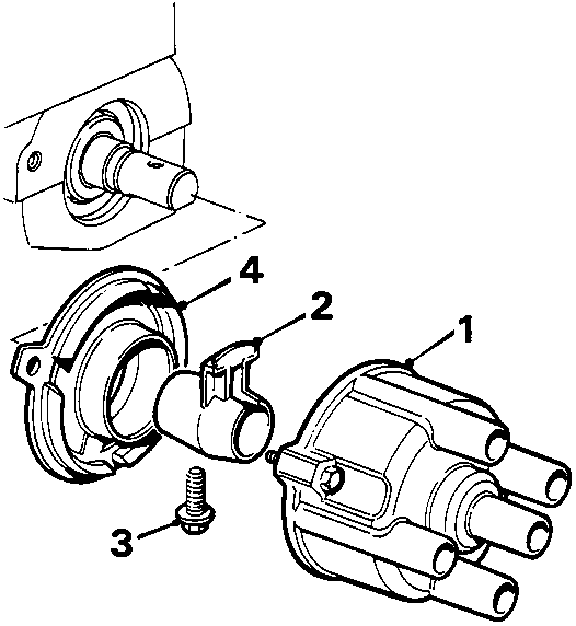
DISTRIBUTOR CAP AND ROTOR ARM
- Distributor cap
- Rotor arm
- Retaining screw
- Anti - flash shield
The distributor cap, carrying a central carbon brush and four h.t. lead pick - ups, is located at No. 4 cylinder end of the camshaft cover and surrounds the rotor arm. The rotor arm is secured by a retaining screw to a 'D' shaped stub shaft, which is press fitted into a vibration absorbing bush in the camshaft, and is protected from contamination by an anti - flash shield which incorporates an oil drain.
Fuel system
ECU
The MEMS system is controlled by the ECU which is located in the engine compartment on the L.H. wing valance to the rear of the battery.
The ECU is an adaptive unit and can learn the load and wear characteristics of a particular engine.
The ECU remembers and updates two main engine requirements when the engine is fully warm:
- The idle stepper position required to achieve the specified idle speed.
- The fuelling change or offset required to achieve a set oxygen sensor voltage.
The stepper position is used as a reference to update the amount of stepper motor movement required to achieve the specified idle speed under all conditions.
The fuelling offset is required to enable the system when not in closed loop control to provide the correct fuelling and while in closed loop control to prevent having to apply excessive adjustments to the fuelling which can adversely affect the emissions and driveability.
Note: After fitting a different ECU, a full tune procedure must be carried out using Microcheck.
Parts & tools for this job For Rover Coupé, Cabriolet & Tourer
- PARTEngine gasket setSearch: Rover Coupé, Cabriolet & Tourer engine gasket set
- TOOLTorque wrenchSearch: 3/8 inch torque wrench
- TOOLFeeler gauge setSearch: feeler gauge set
Links open Amazon search results in a new tab. As an Amazon Associate I earn from qualifying purchases.