
900 L4-1985cc 2.0L (1982)
Oxygen Sensor Relay: Description and Operation
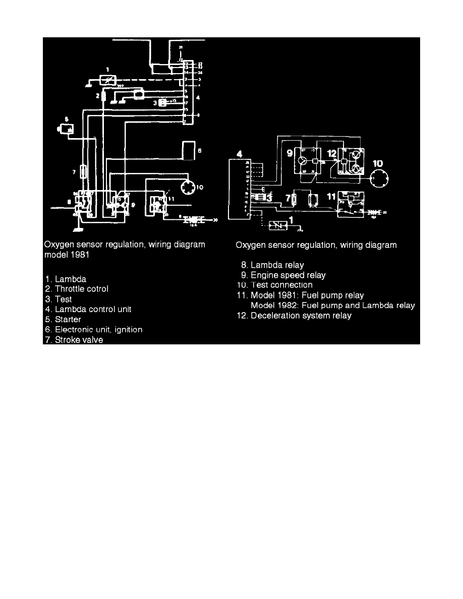
Fig.13 - Oxygen Sensor Regulated Continuous Injection System Electrical Diagram
Current to oxygen sensor regulating relay is supplied from pump relay when fuel pump is operating and, from terminal 30 via starter motor for
1979-81 models. Therefore, power goes to terminal 8 of control unit and terminal 15 via modulating valve. On 1982 models, fuel pump and
oxygen sensor regulating relay are integrated into one relay.
Oxygen sensor is connected to terminal 2 of control unit and is grounded through exhaust manifold. Cable to oxygen sensor is provided with a
suppressor harness which is connected to terminal 4. A rest circuit with a connector piece is included to enable pulse measuring equipment to be
connected. The connector piece is located at, relay holder and cables run to terminal 17 of control unit and terminal 15 in ignition system primary
circuit.