
SW1 L4-1.9L SOHC VIN 8 (1996)
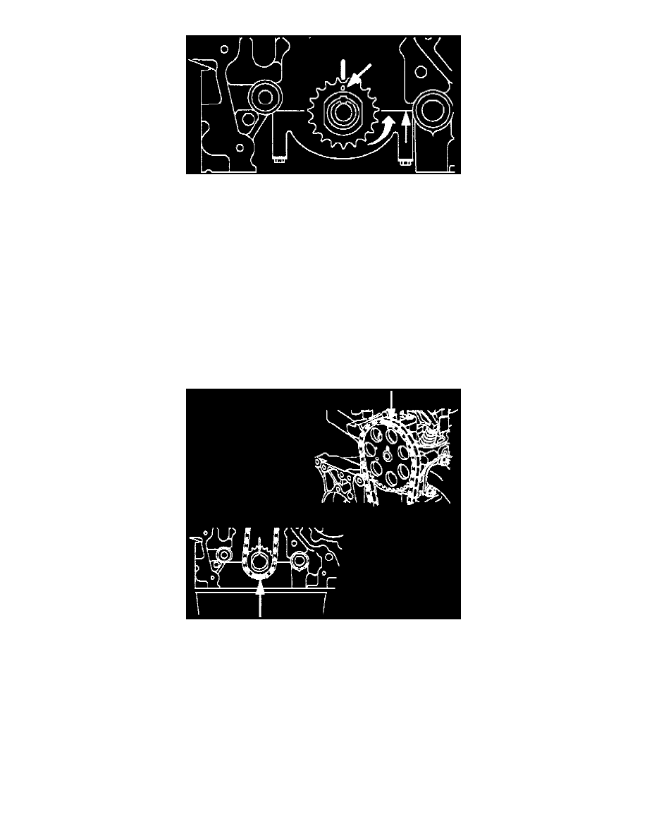
Fig. 18 Crankshaft Sprocket & Block Timing Mark.
Timing Chain, Sprockets, Guides and Tensioner Installation
1. Assemble the timing chain, sprockets, guides and tensioner:
a. Verify that the crankshaft is positioned 90 degrees clockwise past TDC (viewed from accessory drive belt end of crankshaft). The crankshaft
key way sprocket timing mark must be aligned with the cylinder block main bearing cap split line to prevent piston and valve damage.
b. If required, bring the camshaft up to number one TDC. The camshaft can be verified at TDC by loosely installing the sprocket and rotating the
sprocket until the timing pin (3/16 in. drill) can be installed. The dowel pin in the camshaft will be located at the 12 o'clock position. Wrench
flats 21 mm (7/8 in.) are installed on the camshaft to assist with rotating the cam slightly or by installing the sprocket and bolt. Only turn the
camshaft clockwise to prevent intake and exhaust valve damage. The camshaft sprocket and bolt will have to be installed if the camshaft must
be rotated more than a few degrees.
c. Rotate the crankshaft 90 degree counterclockwise (viewed from accessory drive belt end of crankshaft) up to number one TDC. The crankshaft
sprocket timing mark will align with cylinder block timing mark.
Fig. 19 Timing Chain Installation.