
SW1 L4-1.9L SOHC VIN 8 (1996)
IMPORTANT:
If wires are broken inside insulation, outside of insulation may appear to be thin in one area stretched or discolored.
8.
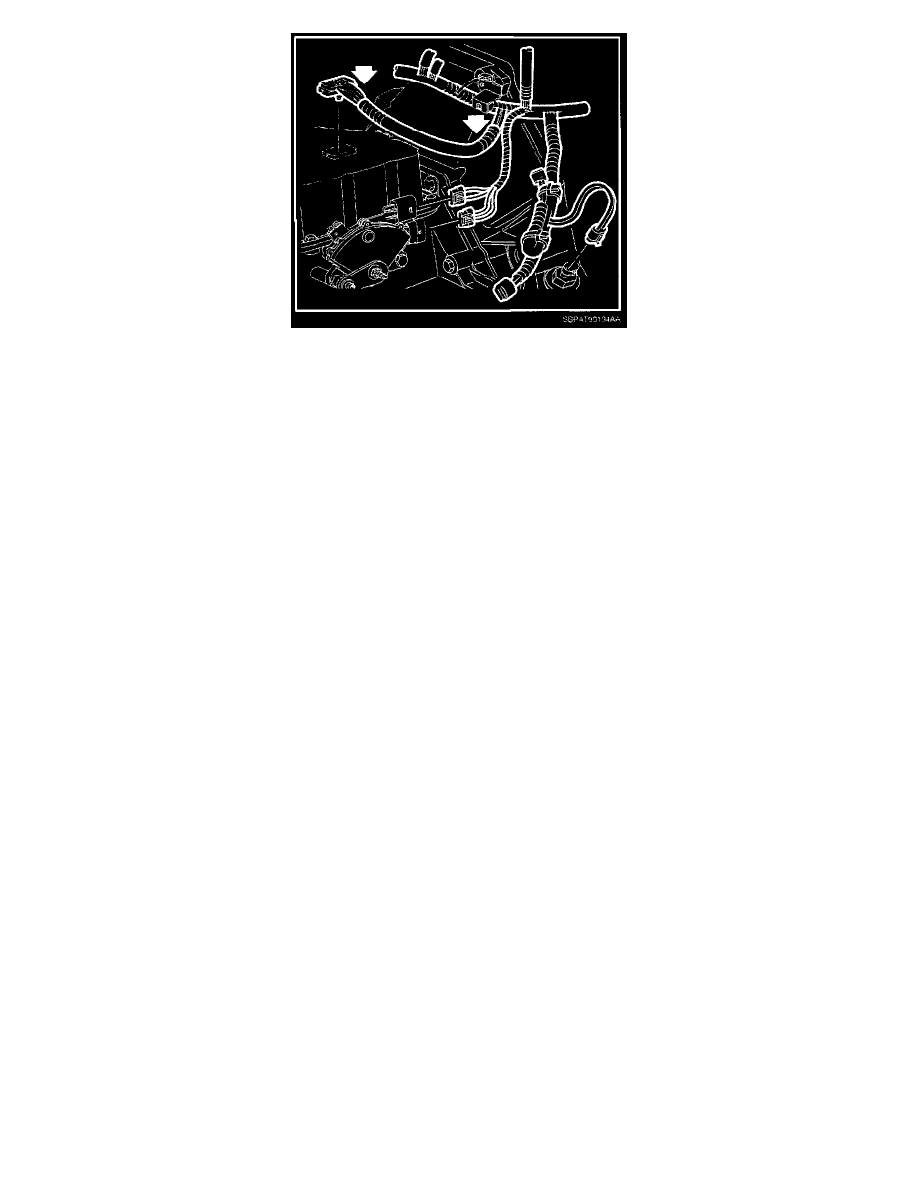
Visually inspect circuits associated with DTC. Inspect wires for damaged or deformed insulation from transaxle electrical connector to main
engine harness (up to 25cm [10 in.] away from connector).
^
If there is visual evidence of wire damage and the location of the open circuit can be identified continue with next step.
^
If there is no visual evidence of wire damage physically inspect each wire by sliding fingers along entire length of wire and feel for
abnormalities or depressions.
-
If wire damage is located during physical inspection, continue with next step.
-
If no wire damage is located during physical inspection, continue to step 10.
IMPORTANT:
When splicing in new connector, stagger crimp-and-seal connectors so they are not all in same location. Staggering crimp-and-seal connectors will
allow for a better finished look.
9.
Once location of open circuit is identified, replace transaxle connector in its entirety (all ten circuits) with replacement transaxle connector (P/N
21024415).
9.1
Cut transaxle connector circuit branch within 38 mm (1.5 in.) of main harness to ensure any other possibly affected circuits are repaired.
Discard transaxle connector.
9.2
Remove insulation from ends of cut wires and new transaxle connector harness. Recommended strip length is 4.8 mm (3/16 in.) for 12-20
gauge wire and 9.5 mm (3/8 in.) for 22 gauge wire so it can be folded in half. Care must be used when stripping wire to prevent cutting the
wire strands.