
VUE AWD V6-3.5L VIN 4 (2004)
5.
Cut two 6 in (15.22 cm) pieces of 5/16 in (0.79 cm) outside diameter brake pipe.
Important:
To aid in sliding the smaller diameter hose over the cooler line pipes, lubricate the oil cooler lines with liquid soap.
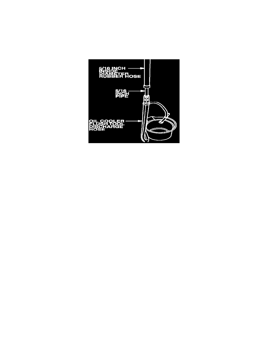
6.
Install a 6 in (15.24 cm) piece of 5/16 in (0.79 cm) inside diameter rubber hose to the cut end of each cooler line and secure with hose clamps.
7.
Flare one end of each piece of the cut brake pipe.
8.
Install a flare nut over each piece of the cut brake pipe.
9.
Slide the end of the rubber hose connected to the oil cooler line over the non-flared end of the cut brake pipe. Secure with a hose clamp. Perform
the same procedure for the second piece of hose/cooler line combination and cut brake pipe.
10.
Using the J35944-13 measuring cup, fill the oil cooler flush tool tank with 21 oz (621 ml) of Kent-Moore J35944-22 Biodegradable Flushing
Fluid.
11.
Secure the cap on the tank and pressurize the tank with shop air to 80-120 psi (551-827 kpa).
12.
Attach the discharge hose to the oil cooler pipe assembly that connects to the top fitting of the oil cooler. Clip the opposite end to an approved
container.
13.
Hang the tool under the vehicle and attach the pressure hose from the flushing tool to the remaining oil cooler pipe assembly.
14.
With the water valve off, attach the water hose to the water supply (hot water, if available). Turn on the water supply.
Important:
If water does not flow through the oil cooler, it is completely plugged and must be replaced.
15.
Turn the water valve located on the cooler flushing tank ON to allow water to flow through the oil cooler for 10 seconds.
16.
Depress the trigger on the cooler flushing tank. Slide the holding clip over the trigger and flush the cooler for two minutes. While flushing the
cooler, attach an air supply to the air valve on the plumbing of the flushing tool for five seconds at 15-20 second intervals to create a surging
action to help clean the oil cooler.
17.
After flushing for two minutes, turn the water valve on the flushing tool OFF and release the trigger.
18.
Swap connections at the tool flare fittings, attaching the discharge hose to the lower cooler fitting and the pressure hose to the upper cooler fittings.
19.
Repeat Steps 15 and 16.
20.
After flushing for two minutes, release the trigger and allow the water to flow through the oil cooler assembly for one minute.
21.
Turn off the water valve on the flushing tool and turn off the main water supply.
22.
Attach the air supply to the air valve on the plumbing of the flushing tool (not the tank valve) and dry the system out with shop air for two full
minutes, or longer if required. The system is dry when no more moisture is visible in or leaving the discharge hose.