seat Workshop Repair Guides

SEAT Workshop Service and Repair Manuals

Assembly > < 02J Gearbox: Dismount and assemble
Dismounting
Dismounting
–  Extract the cover from the engine.
  Note!
To carry out this work, it is necessary to remove the ground strip from the battery. For this purpose, you must check whether the vehicle has a coded radio on board, where appropriate you should consult anti-theft code.
   
–  With the ignition disconnected, release the ground strip from the battery.
–  Remove the inlet flexible tube -1-, the connecter -2- and the flexible tube -3- the air quantity meter.
–  Extract the air filter casing by removing the bolts -4- and -5- → Rep. Gr.24.
–  Remove the connector for the speedometer transmitter -arrow 1-.
  A37-0192
–  Remove the connector for the reverse gear lights -arrow 2-.
  V34-2681
–  Disconnect the cable for selection -A- and the gear connection cable from the gearbox -B- by levering out with a fixed key for 16 mm.
  N34-0860
–  Extract the cable holder for the gear connection in the gearbox -arrows- if necessary, first remove the flexible pressure tube from the hydraulic control system for the clutch.
  V34-2671
–  Extract the counterweight -1- from the gear stick, by disconnectingthe block of the return lever -2-.
  N34-0895
–  Extract the clutch pump, from the gearbox casing, move it and attach it again.
  Note!
t  Do not work the clutch pedal during the repair work
t  Do not open the brake pressure system.
  V34-2672
–  Extract the cable holder from the start engine -1-.
–  Dismount the upper bolt -2- that attaches the starter to the engine block.
–  Extract the ground strip and the nut that connects the cable to the upper bolt for attaching the engine/gearbox.
–  Dismount the upper bolts that attach the gearbox to the engine.
–  Disconnect the flexible tubes and cables that might be present in the area of the engine where the rings are fitted that are used to support the drive engine unit.
  N34-0718
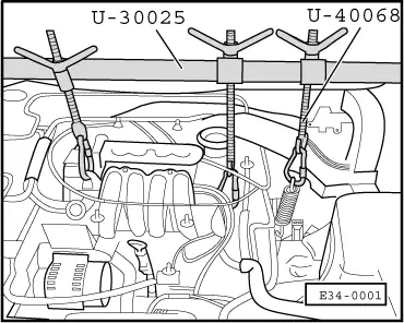
–  Assemble the attachment bar -U-30025- and the tool -U-40068- over the engine span.
–  Connect the bar braces -U-30025- to the engine.
–  Connect the tool -U-40068- over the gearbox.
–  Pre-tighten the drive engine unit using the screws from the tools -U-30025- and -U-40068-.
–  Dismount the central, left and the right soundproofing covers part of the case through the lower part of the drive engine unit, if they are installed.
–  Dismount the flaps for the front bumper.
–  Dismount the intercooler and the inlet and outlet pipes → Rep. Gr.21.
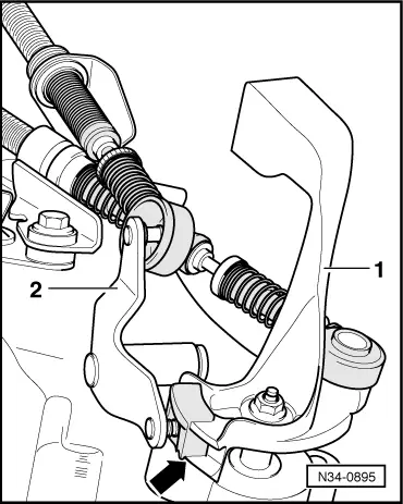
–  Remove the clip for the power steering piping that attaches it to the gearbox.
–  Dismount the right-hand heat insulating plate through the lower part of the engine, for the homokinetic seal, if it has one.
–  Turn the wheels to the left.
–  Disconnect the right-hand side drive train from the gearbox side flanged axle, move it to one side and secure it into place.
–  Dismount the left-hand drive train → Rep. Gr.40.
  E34-0001
–  Extract the small protective plate -A- from the engine wheel located behind the right flanged axle -arrows- if it were assembled.
–  Extract the lower protective plate for the engine wheel, if it were assembled.
–  Remove the exhaust system, dismount it from the unit holder, if necessary → Rep. Gr.26.
–  Dismount the starter → Rep. Gr.27.
  V34-3005
–  Extract the back support for the drive engine unit -arrows-.
–  Dismount the front.
  E34-0208
–  Extract the support block from the rear part of the gearbox -arrows-.
  E34-0209
–  Put the drive engine unit into a sloped position, to do so, lower it using the left screw from the tool -U-30025-.
  E34-0001
–  Move the driver motor forwards with the tool -T20111-.
–  Dismount the lower bolts for engine/gearbox connection.
–  Remove the gearbox from the centring sleeves and lower it using the screw -U-40068-.
–  Avoid the part of the differential in the unit holder and lower it down to the bottom.
  Note!
When the gearbox lowered into place, the tubes for the power steering must be taken into account.
  E34-0212

Assembly > < 02J Gearbox: Dismount and assemble