
Leon Mk1
| Secondary shaft: Dismounting and assembling |
| t | If it is necessary to assemble new pinions, consult section Identification initials, assignation of groups, reductions, amounts for filling → Chapter |
| t | The secondary shaft must always be adjusted when parts have been replaced that might affect the position of the tapered roller bearings. Consult the Chart for Adjustments → Chapter. |
| t | Dismounting the secondary shaft → Fig. and → Fig. |
| Montageübersicht |
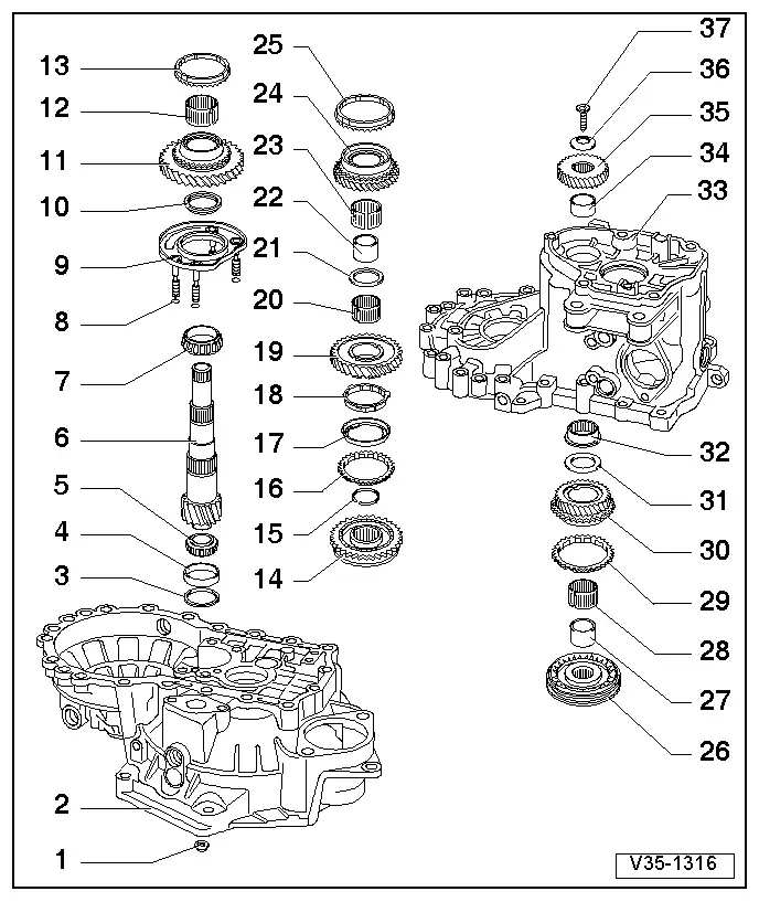
| 1 - | Nut. 25 Nm + 90º |
| q | 4 units |
| q | For attaching the secondary shaft |
| 2 - | Clutch casing |
| 3 - | Adjustment washer |
| q | For the secondary shaft |
| q | Finding the thickness → Chapter |
| 4 - | Outer track, tapered roller bearing |
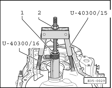
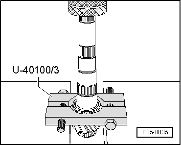
| q | Dismounting → Fig. |
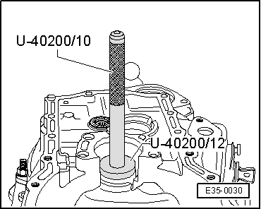
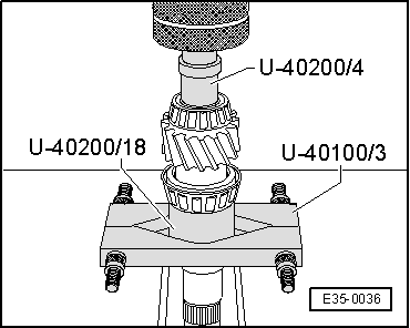
| q | Assembling → Fig. |
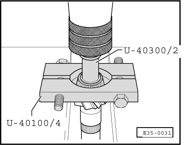
| 5 - | Tapered roller bearing |
| q | Dismounting → Fig. |
| q | Assembling → Fig. |
| 6 - | Secondary shaft |
| q | It is coupled with the pinion for the control drive trains; in the event of replacement they should be changed together. |
| q | In the event of replacement → Chapter, Identification initials, assignation of groups, reductions, amounts for filling |
| q | Adjustment for the secondary shaft → Chapter |
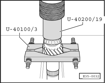
| 7 - | Tapered roller bearing |
| q | Dismounting → Fig. |
| q | Assemble → Fig. |
| 8 - | Seal ring |
| q | 4 units |
| q | Always replace |
| q | For the bolts for attaching the cover for the secondary shaft bearing → Item |
| 9 - | Cover for the secondary shaft bearing |
| q | It includes the outer track for the tapered roller bearing → Item. |
| q | The cover for the secondary shaft bearing must be replaced together with the outer track for the tapered roller bearing and the tapered roller bearing → Item. |
| 10 - | Stop washer |
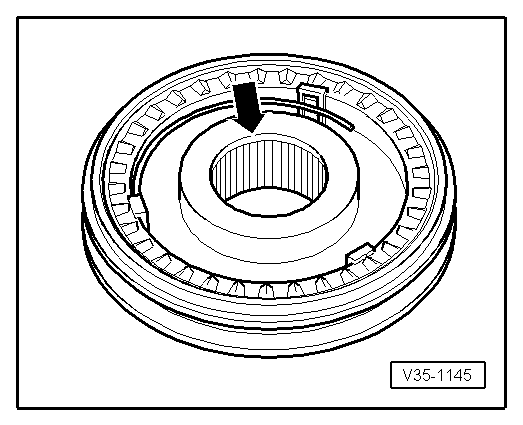
| q | The edge of the washer must be facing towards the tapered roller bearing. |
| 11 - | 1st gear pinion |
| q | Before assembling the 1st gear pinion assemble the stop washer → Item. |
| 12 - | Needle bearing for 1st gear pinion |
| 13 - | Synchroniser ring for 1st gear |
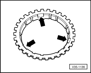
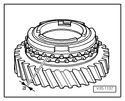
| q | Identification → Fig. and → Fig. |
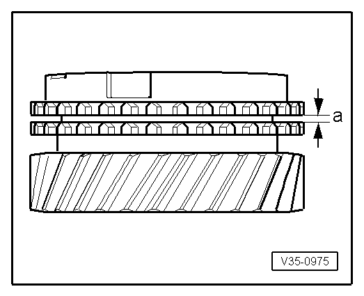
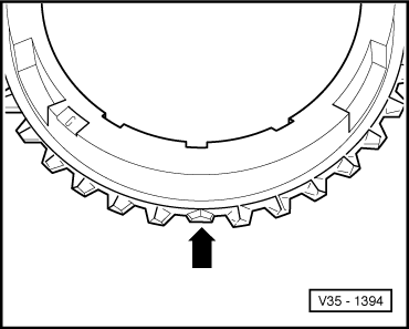
| q | Control for wear → Fig. |
| q | Check that the flanges have no signs of wear. |
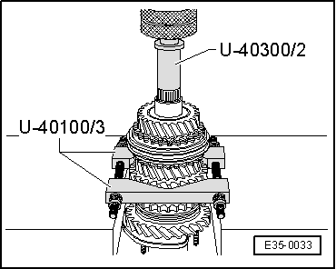
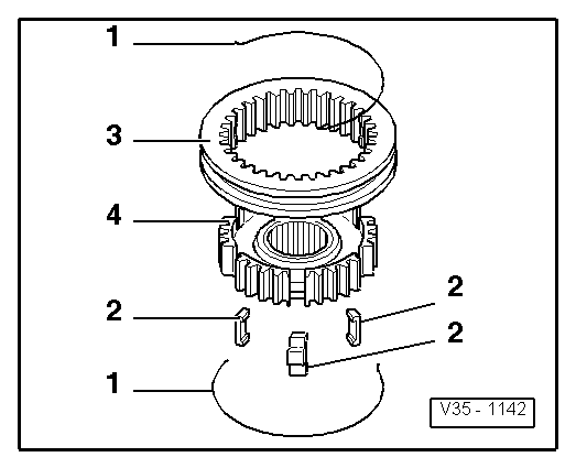
| 14 - | Synchroniser unit for 1st and 2nd gears |
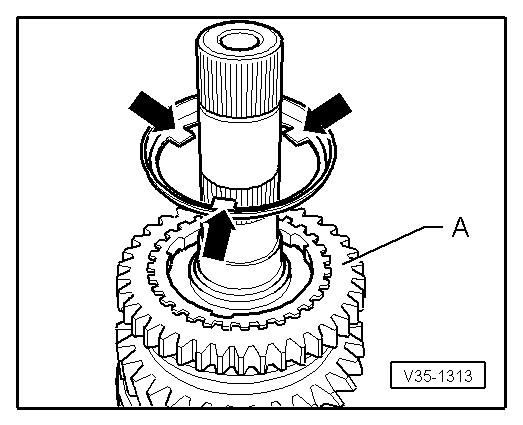
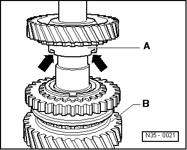
| q | Dismounting the secondary shaft → Fig. |
| q | Dismounting → Fig. |
| q | Assembling the components → Fig. and → Fig. |
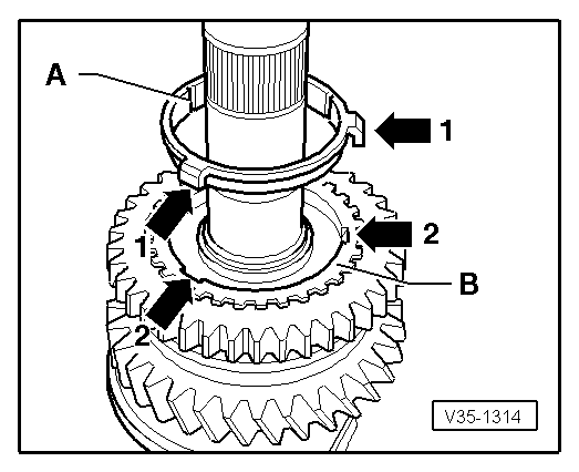
| q | Position for assembly → Fig. |
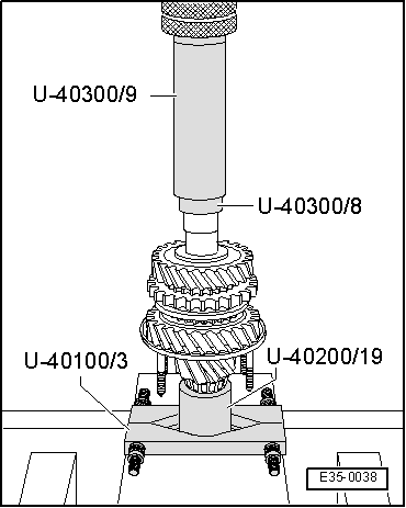
| q | Assembly of the secondary shaft → Fig. |
| 15 - | Safety ring |
| q | Use tool -A-81124- for extracting the safety ring. |
| q | Always replace. |
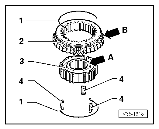
| 16 - | Outer synchroniser ring for 2ndgear |
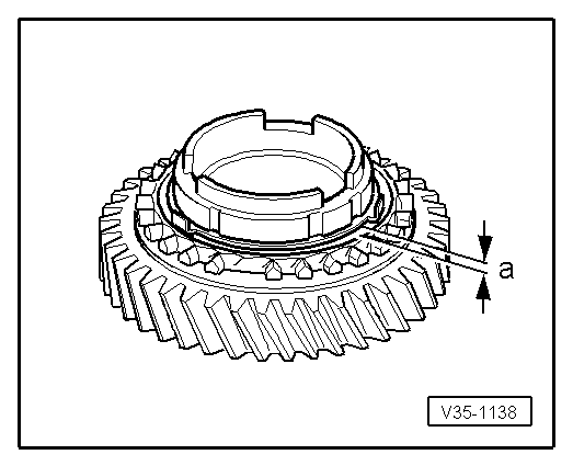
| q | Identification → Fig. and → Fig. |
| q | Control for wear → Fig. |
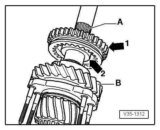
| q | Assembly: the trimmings of the synchroniser ring must always be fitted with the pins in the synchroniser unit for 1st and 2nd gear → Item. |
| 17 - | Intermediate synchroniser ring for 2nd gear |
| q | Place it on the outer synchroniser ring → Item |
| q | Position for assembly → Fig.. |
| q | Replace it if it shows signs of wear or cracks. |
| 18 - | Inner synchroniser ring for 2nd gear |
| q | Identification → Fig. and → Fig. |
| q | Control for wear → Fig. |
| q | Check that the flanges do not show any signs of wear. |
| q | Position for assembly → Fig. |
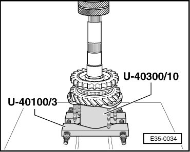
| 19 - | 2nd gear pinion |
| q | Position for assembly → Fig. |
| 20 - | Needle bearing for 2nd gear pinion |
| 21 - | Stop washer |
| 22 - | Sleeve for needle bearing |
| q | Dismounting, together with the 2nd gear pinion → Fig. |
| q | Assembling → Fig. |
| 23 - | Needle bearing for 3rd gear pinion |
| 24 - | 3rd gear pinion |
| 25 - | Synchroniser ring for 3rd gear |
| q | Check for wear → Fig. |
| 26 - | Synchroniser unit for 3rd and 4th gears |
| q | Dismounting the secondary shaft → Fig. |
| Dismounting the synchroniser unit → Fig. |
| q | Assembling the components → Fig. and → Fig. |
| q | Position for assembly → Fig. |
| q | Assembly for the secondary shaft → Fig. |
| 27 - | Sleeve for needle bearing |
| q | Dismounting together with the synchroniser unit for 3rd and 4th gears → Item, → Fig. |
| q | Assembling → Fig. |
| 28 - | Needle bearing for 4th gear pinion |
| 29 - | Synchroniser ring for 4th gear |
| q | Check for wear → Fig. |
| 30 - | 4th gear pinion |
| 31 - | Stop washer |
| 32 - | Needle bearing for the secondary shaft |
| q | Dismounting and assembling → Chapter |
| 33 - | Gearbox casing |
| 34 - | Sleeve for needle bearing |
| q | Dismounting → Fig. |
| q | Assembling → Fig. |
| 35 - | 5th gear pinion |
| q | Dismounting and assembling → Chapter |
| 36 - | Plate spring |
| q | Position for assembly: the concave side must remain facing towards the 5th gear pinion. |
| 37 - | Bolt for attaching the 5th gear pinion |
| q | The head of the bolt includes a housing for the plate spring → Item |
| q | Assembly → Chapter |
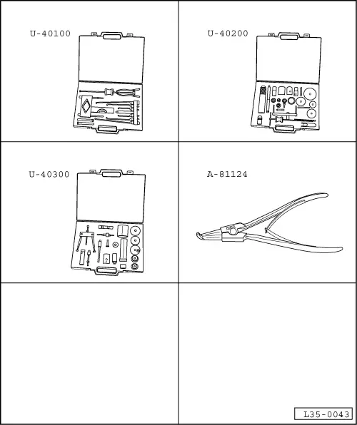
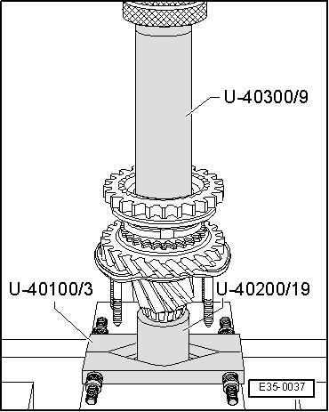
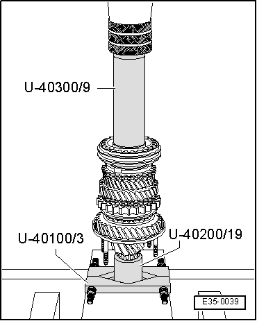
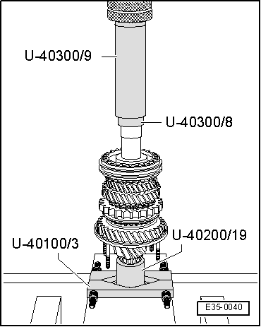
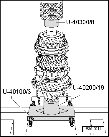
| Special tools and workshop equipment required |
| t | Case for extractors for gearboxes -U-40100- |
| t | Gearbox repair case -U-40200- |
| t | Gearbox repair case -U-40300- |
| t | Pliers for opening elastic rings -A-81124- |
|
|
|
|
|
|
|
|
|
|
|
|
|
|
|
|
| Synchroniser ring | Measurement “a” in a new synchroniser | Wear limit |
| 1st gear 3rd gear 4th gear | 1.0 … 1.7 mm | 0.5 mm |
|
|
|
|
|
|
|
|
|
|
|
|
|
|
| Synchroniser ring | Measurement “a” in a new synchroniser | Limit for wear |
| 2nd gear | 1.2 … 1.8 mm | 0.5 mm |
|
|
|
|
| Synchroniser ring | Measurement “a” in a new synchroniser | Limit for wear |
| 2nd gear | 0.75 … 1.25 mm | 0.3 mm |
|
|
|
|
|
|
|
|
|
|
|
|
|
|
|
|
|
|