
Leon Mk1
| Assembly diagram - hydraulic |
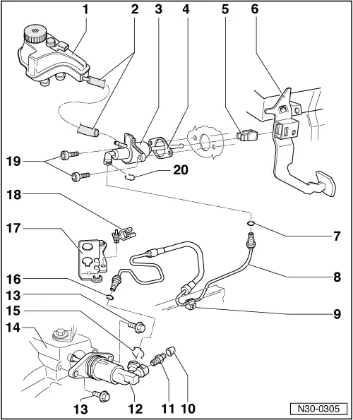
| 1 - | Brake fluid deposit |
| 2 - | Circulation hose |
| 3 - | Clutch pump |
| q | Removing and fitting → Chapter |
| 4 - | Gasket |
| q | Always renew |
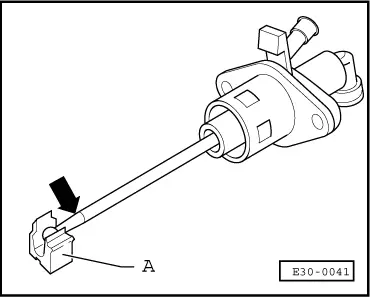
| 5 - | Housing |
| q | Replace only with the clutch pump removed |
| q | Remove → Fig. |
| q | Fit → Fig. |
| 6 - | Clutch pedal |
| q | Removing and fitting → Chapter |
| 7 - | O-ring |
| q | Always renew |
| q | Fit in the tube connection |
| q | Insert with brake fluid |
| 8 - | Pipes and hose |
| q | Correspondance → Parts Catalogue |
| 9 - | Pipework support |
| q | Fixed onto the bodywork |
| 10 - | Protective cap |
| 11 - | Air bleeding valve |
| q | Bleeding air from the clutch system → Chapter |
| 12 - | Clutch coil |
| Before it is removed, the following pieces must be removed: |
| q | Connection cable for selector rod shaft → Item |
| q | Return lever → Item |
| q | After fitting, the gearbox actioning mechanism must be adjusted → Chapter |
| 13 - | Combi bolt |
| q | 25 Nm |
| q | Always renew |
| 14 - | Gearbox |
| 15 - | Retaining clip |
| q | Remove levering with a screwdriver |
| 16 - | O-ring |
| q | Fit in the tube connection |
| q | Insert with brake fluid |
| 17 - | Counterhold |
| 18 - | Hose support |
| q | Counterhold for gearbox control cables must be attached |
| 19 - | Allen head bolt |
| q | 25 Nm |
| 20 - | Retaining clip |
| q | Remove levering with a screwdriver |
|

|
|
|