
Leon Mk1
| Input shaft: dismantling and assembling |
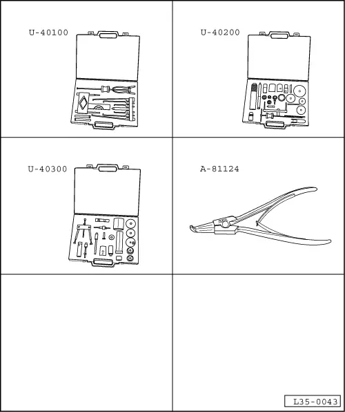
| Special tools and workshop equipment required |
| t | Gearbox extractor set -U-40100- |
| t | Gearbox repair set -U-40200- |
| t | Gearbox repair set -U-40300- |
| t | Circlip opening pliers -A-81124- |
 Note!
Note!| t | Whenever new gears are fitted consult the technical data → Chapter, Code letters, group numbers, ratios, filling quantities. |
| t | The input shaft must be adjusted whenever elements have been replaced which could affect the position of the roller bearings. Refer to Adjustment chart → Chapter. |
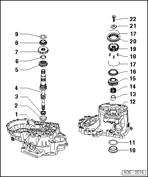
| 1 - | Clutch housing |
| q | Repairing → Chapter |
| 2 - | Outer track, roller bearing |
| q | Remove → Fig. |
| q | Fit → Fig. |
| 3 - | Roller bearing |
| q | Remove → Fig. |
| q | Fit → Fig. |
| 4 - | Input shaft |
| q | Adjusting → Chapter |
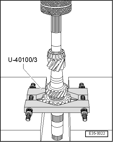
| 5 - | 3rd gear |
| q | Remove → Fig. |
| q | Fit → Fig. |
| q | Assembly position: the collar must be facing the 4th gear |
| 6 - | Safety ring |
| q | Use tool -A-81124- to remove the circlip |
| q | Always renew |
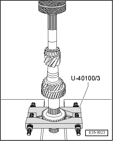
| 7 - | 4th gear |
| q | Remove together with the roller bearings → Item, stop washer → Item and bush → Item → Fig. |
| q | Fit → Fig. |
| q | Assembly position: the collar must be facing the 3rd gear |
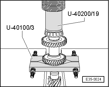
| 8 - | Roller bearing |
| q | Remove → Fig. |
| q | Fit → Fig. |
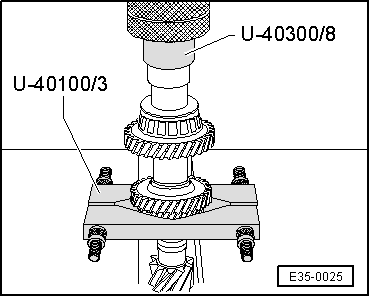
| 9 - | Stop washer |
| q | Remove → Fig. |
| q | Fit → Fig. |
| 10 - | Outer track, roller bearing |
| q | Remove → Fig. |
| q | Fit → Fig. |
| 11 - | Shim |
| q | For the input shaft |
| q | Determine thickness → Anchor |
| 12 - | Gearbox casing |
| q | Repairing → Chapter |
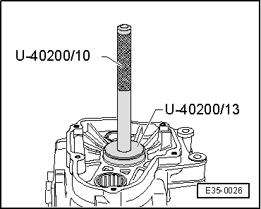
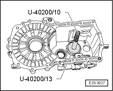
| 13 - | Needle bearing bush |
| q | Remove → Fig. |
| q | Before assembling, fit the stop washer → Item |
| q | Fit → Fig. |
| 14 - | Needle roller bearing |
| 15 - | Sliding 5th gear |
| q | Remove with the 5th gear syncromesh assembly → Chapter |
| 16 - | Syncromesh ring 5th gear |
| q | Check wear → Anchor |
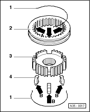
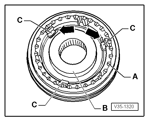
| 17 - | Spring |
| q | Fit → Fig. |
| 18 - | Locking keyways |
| q | Fit → Fig. |
| 19 - | Syncromesh hub |
| q | Fit → Fig. |
| 20 - | Sliding sleeve 5th gear |
| q | Fit → Fig. |
| 21 - | Plate spring |
| q | Assembly position: The concave side should be facing the 5th gear → Chapter |
| 22 - | Securing screw for 5th gear |
| q | 80 Nm |
| q | The screw head incorporates a housing for the plate spring → Item |
| q | Fit → Chapter |
|
|
|
|
|
|
|
|
|
|
|
|
|
|
|
|
|
|
|
|
Note!
|
|
|
|
|
|