
Leon Mk1
| Main shaft: dismounting and assembling |
| t | If it is necessary, assemble new pinions, consult section for Identification initials, assignation of groups, reductions, amounts for filling Group → Chapter. |
| t | The main shaft must be adjusted whenever parts have been replaced that may affect the position of the tapered roller bearings. Consult the Adjustment Chart → Chapter. |
| Assembly Chart |
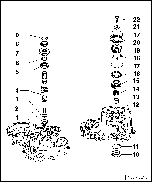
| 1 - | Clutch casing |
| 2 - | Outer track, tapered roller bearings |
| q | Dismounting → Fig. |
| q | Assembling → Fig. |
| 3 - | Tapered roller bearing |
| q | Dismounting → Fig. |
| q | Assembling → Fig. |
| 4 - | Main shaft |
| q | Adjusting the main shaft → Chapter |
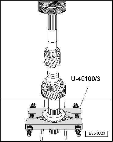
| 5 - | 3rd gear pinion |
| q | Dismounting → Fig. |
| q | Assembling → Fig. |
| q | Position for assembly: the collar must remain facing towards the 4th gear pinion. |
| 6 - | Safety ring |
| q | Use tool -A-81124- for extracting the safety ring. |
| q | Always replace |
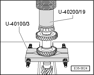
| 7 - | 4th gear pinion |
| q | Dismount it together with the tapered roller bearing → Item, the stop washer → Item and the sleeve for the needle bearing → Item, → Fig. |
| q | Assembling → Fig. |
| q | Position for assembly: the collar must remain facing towards the 3rd gear pinion. |
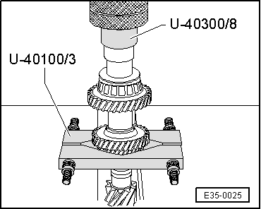
| 8 - | Tapered roller bearing |
| q | Dismount it together with the 4th gear pinion → Item, the stop washer → Item and the sleeve for the needle bearing → Item, → Fig. |
| q | Assembling → Fig. |
| 9 - | Stop washer |
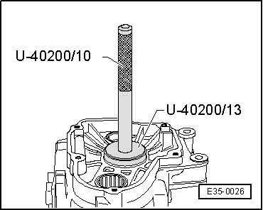
| 10 - | Outer track, tapered roller bearing |
| q | Dismounting → Fig. |
| q | Assembling → Fig. |
| 11 - | Adjustment washer |
| q | For the main shaft |
| q | Finding the thickness → Chapter |
| 12 - | Gearbox casing |
| 13 - | Sleeve for needle bearing |
| q | Dismount together with the 4th gear pinion → Item, the tapered roller bearing → Item and the stop washer → Item, → Fig. |
| q | Before assembling it, put the stop washer into place → Item |
| q | Assembling → Fig. |
| 14 - | Needle bearing |
| 15 - | 5th gear pinion |
| q | Dismount it together with the 5th gear synchroniser unit → Chapter |
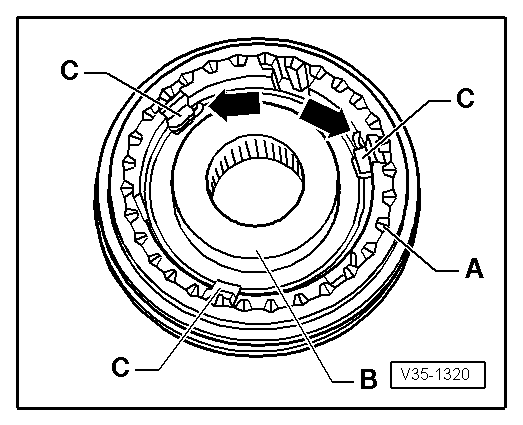
| 16 - | 5th gear synchroniser ring |
| q | Check the wear → Chapter |
| 17 - | Spring |
| q | Position for assembly → Fig. |
| 18 - | Blocking pins |
| q | Assembling → Fig. |
| 19 - | Synchronised boss |
| q | Assembling → Fig. |
| 20 - | Movable sleeve for 5th gear |
| q | Assembling → Fig. |
| 21 - | Plate spring |
| q | Position for assembly: the concave side must remain facing towards the 5th gear pinion → Chapter |
| 22 - | Bolt for attaching the 5th gear pinion. 80 Nm |
| q | The head of the bolt has a slot for housing the plate spring → Item |
| q | Assembly → Chapter |
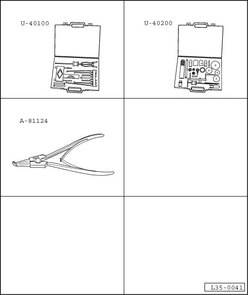
| Special tools and workshop equipment required |
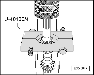
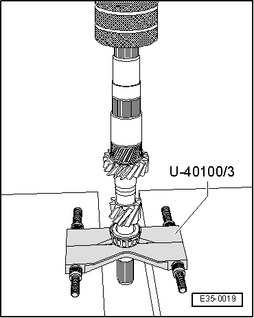
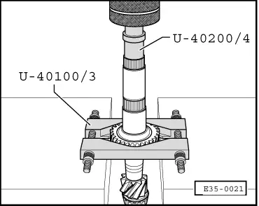
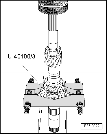
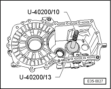
| t | Case for extractors for gearboxes -U-40100- |
| t | Gearbox repair case -U-40200- |
| t | Pliers for opening elastic rings -A-81124- |
|
|
|
|
|
|
|

|
|
|
|
|
|
|
|
|
|
|
|
|
 Note!
Note!
|
|
|

|
|
|