seat Workshop Repair Guides

SEAT Workshop Service and Repair Manuals

Input shaft: adjustment > < Main shaft: dismounting and assembling
Main shaft: adjusting
   
Main shaft: adjusting
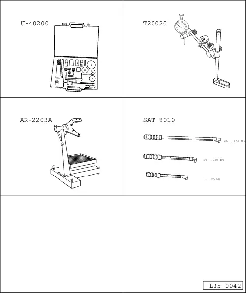
Special tools and workshop equipment required
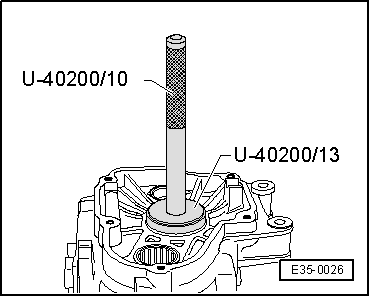
t  Case for repairing gearboxes -U-40200-
t  All-purpose support for tester -T20020-
t  Support column for gearbox-differential -AR-2203A-
t  Dynometric keys -SAT 8010-

Adjust the main shaft when any of the following components have been replaced:
t  Gearbox casing
t  Clutch casing
t  Main shaft
t  4th gear pinion
t  Tapered roller bearings in the main shaft
So as to avoid unnecessary adjustment work, consult the Chart for Adjustment → Chapter.
   
–  Assemble the outer track of the tapered roller bearing for the main shaft in the gearbox casing without the adjustment washer, using tool -U-40200/10- and tool -U-40200/13-.
–  Place the main shaft into its housing in the clutch casing.
–  Assemble the gearbox casing over the clutch casing and tighten the bolts for attaching them.
Tightening torque: 25 Nm + 90º
  E35-0027
–  Place tool -T20020- with a tester over the gearbox casing. Place the end of it over the main shaft.
–  Turn the main shaft a few times in order to settle the tapered roller bearings.
–  Adjust the tester to “0” with a prior stress of 1 mm.
  Note!
The adjustment to “0” for the tester must be repeated each time that the measurement is made, otherwise, the tester will not go back to the initial position.
  E35-0028
–  On the lower part of the gearbox, put pressure on the main shaft in the direction of the tester.
–  Note the reading given on the tester (Example: 1.21 mm).
  Note!
The tester does not return to the initial position.
t  The adjustment washer needed is found by means of the following Table → Anchor.
Example:
t  Set in the tester = 1,21 mm.
t  According to the Table for a set for the main shaft from 1.200 to 1.224 mm, a thickness of 1.175 mm would correspond to it.
Table of adjustment washers
  E35-0013
HeightAdjustment washer
measured for bearing set (mm)Thickness (mm)Spares No.
0.671 … 0.699
0.700 … 0.724
0.725 … 0.749
0.650
0.675
0.700
02A 311 140
02A 311 140 A
02A 311 140 B
0.750 … 0.744
0.775 … 0.799
0.800 … 0.824
0.725
0.750
0.775
02A 311 140 C
02A 311 140 D
02A 311 140 E
0.825 … 0.849
0.850 … 0.874
0.875 … 0.899
0.800
0.825
0.850
02A 311 140 F
02A 311 140 G
02A 311 140 H
0.900 … 0.924
0.925 … 0.949
0.950 … 0.974
0.875
0.900
0.925
02A 311 140 J
02A 311 140 K
02A 311 140 L
0.975 … 0.999
1.000 … 1.024
1.025 … 1.049
0.950
0.975
1.000
02A 311 140 M
02A 311 140 N
02A 311 140 P
1.050 … 1.074
1.075 … 1.099
1.100 … 1.124
1.025
1.050
1.075
02A 311 140 Q
02A 311 140 R
02A 311 140 S
1.125 … 1.149
1.150 … 1.174
1.175 … 1.199
1.100
1.125
1.150
02A 311 140 TT
02A 311 140 AA
02A 311 140 AB
1.200 … 1.224
1.225 … 1.249
1.250 … 1.274
1.175
1.200
1.225
02A 311 140 AC
02A 311 140 AD
02A 311 140 AE
1.275 … 1.229
1.300 … 1.324
1.250
1.275
02A 311 140 AF
02A 311 140 AG
1.325 … 1.3491.30002A 311 140
02A 311 140
1.350 … 1.3741.32502A 311 140
02A 311 140 A
1.375 … 1.3991.35002A 311 140 A
02A 311 140 A
1.400 … 1.4241.37502A 311 140 A
02A 311 140 B
1.425 … 1.4491.40002A 311 140 B
02A 311 140 B
1.450 … 1.4741.42502A 311 140 B
02A 311 140 C
1.475 … 1.4991.45002A 311 140 C
02A 311 140 C
1.500 … 1.5241.47502A 311 140 C
02A 311 140 D
1.525 … 1.5491.50002A 311 140 D
02A 311 140 D
1.550 … 1.5741.52502A 311 140 D
02A 311 140 E
1.575 … 1.5991.55002A 311 140 E
02A 311 140 E
1.600 … 1.6241.57502A 311 140 E
02A 311 140 F
1.625 … 1.6491.60002A 311 140 F
02A 311 140 F
1.650 … 1.6741.62502A 311 140 F
02A 311 140 G
1.675 … 1.6991.65002A 311 140 G
02A 311 140 G
1.700 … 1.7241.67502A 311 140 G
02A 311 140 H
1.725 … 1.7491.70002A 311 140 H
02A 311 140 H
1.750 … 1.7741.72502A 311 140 H
02A 311 140 J
1.775 … 1.7911.75002A 311 140 J
02A 311 140 J

–  Once the adjustment washer needed has been foand, remove the comparator.
–  Remove the bolts that attach both casings and take out the gearbox casing.
–  Remove the main shaft from the casing.
   
–  Remove the outer track of the tapered roller bearing for the main shaft in the gearbox casing using tool -U-40200/10- and tool -U-40200/13-.
–  Place the adjustment washer with the thickness calculated (in this case, 1.175 mm) into the housing for the outer track of the tapered roller bearing.
  E35-0026
–  Assemble the outer track of the tapered roller bearing of the main shaft in the clutch casing using tool -U-40200/10- and tool -U-40200/13-.
–  Carry out a measurement for control.
Measurement for control
–  Place the main shaft into its housing in the clutch casing.
–  Assemble the gearbox casing over the clutch casing and tighten the bolts for attaching them.
Tightening torque: 25 Nm + 90º
  E35-0027
–  Place the tool -T20020- over the gearbox casing with a tester.
–  Place the end of the tester on the main shaft.
–  Turn the main shaft a few times in order to settle the tapered roller bearings.
–  Adjust the tester to “0” with a pretension of 1 mm.
–  On the lower part of the gearbox, put pressure on the main shaft in the direction of the tester.
–  The bearing play should range between a minimum of 0.01 mm and a maximum of 0.1 mm.
  Note!
If it is not possible to note any play in the bearing, but however the first shaft has quite a visible play that allows a smooth turn, the adjustment is right.
  E35-0013

Input shaft: adjustment > < Main shaft: dismounting and assembling